
Clamping means assembly for a machine tool, and machine tool comprising the clamping means assembly

A fixture and component technology, applied in the direction of metal processing mechanical parts, clamping, manufacturing tools, etc., can solve the problems of high cost and no equipment, and achieve high feed speed, improved processing effect, and more cost-effective effects.

Pending Publication Date: 2019-10-25
SCHAEFFLER TECH AG & CO KG
View PDF7 Cites 2 Cited by
  • Summary
  • Abstract
  • Description
  • Claims
  • Application Information

AI Technical Summary

Problems solved by technology

[0004] However, in production companies, older machine tools are often used, which do not have equipment for generating such vibrations
Purchasing new machine tools will result in high costs

Method used


Image

  • Clamping means assembly for a machine tool, and machine tool comprising the clamping means assembly
  • Clamping means assembly for a machine tool, and machine tool comprising the clamping means assembly

Examples


Embodiment Construction

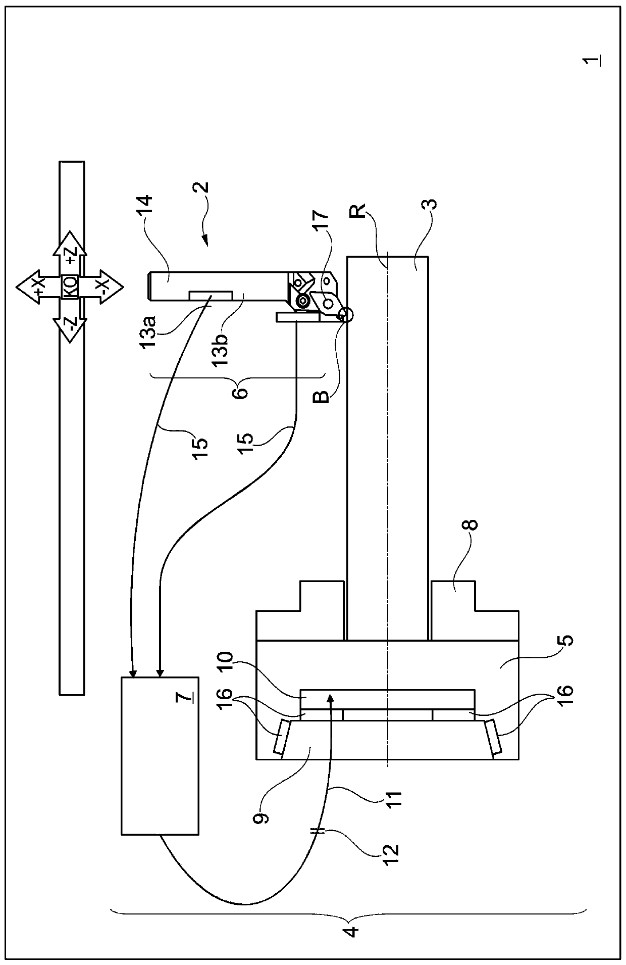
[0029] figure 1 A machine tool 1 with a tool 2 for machining a workpiece 3 is shown as an exemplary embodiment of the invention in a very schematic illustration. Conceptually, the workpiece 3 is rotated during machining about an axis of rotation R, which extends parallel to the Z direction in the coordinate system KO of the machine tool 1 . In the side view shown, the X direction runs perpendicularly to the Z direction in the coordinate system KO. In particular the X-Z plane is shown.

[0030] The tool 2 can be designed, for example, as a boring tool, milling tool, turning tool or broaching tool. In the present embodiment, the tool 2 is realized as a turning tool. The knife 2 has a knife holder 14 with a shank and a head, wherein an indexable blade is arranged on the head as a cutting body 17 .

[0031] The machine tool 1 has a gripper assembly 4 constructed from a sensor assembly 6 , a gripper 5 and a control device 7 . The clamping device 5 has a clamping chuck, in part...


PUM


Abstract

The invention relates to a clamping means assembly (4) for a machine tool (1). The machine tool (1) has a tool (2) for machining a workpiece (3). The clamping means assembly (4) comprises a clamping means (5) which has a machine interface (9) for coupling to the machine tool (1) and a workpiece interface (8) for receiving the workpiece (3), a sensor assembly (6) which is designed to pick up vibrations of the tool (2) in the form of sensor data, and a controller (7) for receiving sensor data of the sensor assembly (6), wherein the clamping means (5) has at least one actuator (10) which is arranged on the clamping means (5), and the controller (7) is designed to actuate the at least one actuator (10) on the basis of the sensor data in order to compensate for the vibrations of the tool (2).

Description

technical field [0001] The invention relates to a clamping assembly for machine tools having the features of the preamble of claim 1 . The invention also relates to a machine tool with the clamp assembly. Background technique [0002] In separate, in particular cutting, machining methods, the machining of the workpiece causes vibrations of the workpiece or the tool. This vibration will be amplified when the feed rate of the tool is adjusted too high during machining. This can lead, for example, to “chatter” during turning operations, in which characteristic, regular chatter patterns or chatter marks are applied to the workpiece, thereby reducing the machining quality on the workpiece. Therefore, it is advantageous to reduce the feed rate during processing from this aspect in order to improve the processing quality. On the other hand, it is desirable to set the feed rate as high as possible in order to achieve the lowest possible machining times. [0003] DE 10 2006 049 8...

Claims


Application Information

Patent Timeline
IPC IPC(8): B23Q3/06B23Q17/09
CPCB23Q3/06B23Q17/0976
Inventor 迈克尔·哈伯策特尔
Owner SCHAEFFLER TECH AG & CO KG
Learn More