Cryogenic Microwave Analyzer

A technology of microwave radiation and microwave filter, applied in instruments, thermometers, scientific instruments, etc., can solve problems such as expensive and difficult reference signals

Active Publication Date: 2022-01-07
IQM FINLAND OY
View PDF7 Cites 0 Cited by
  • Summary
  • Abstract
  • Description
  • Claims
  • Application Information

AI Technical Summary

Problems solved by technology

Essentially every manufactured bolometer can be calibrated individually with some known source of microwave radiation, but it is difficult and expensive to generate the required reference signal at the microwave frequency with the required accuracy

Method used


Image

  • Cryogenic Microwave Analyzer
  • Cryogenic Microwave Analyzer
  • Cryogenic Microwave Analyzer

Examples


Embodiment Construction

[0022] Figure 4 A detector 400 of microwave radiation is shown. The detector comprises a signal input 401 and a detector output 402 . Signal input 401 is a connection through which a signal to be measured can be coupled into the detector using a signal input transmission line. Detector output 402 is a connection through which the detector can be coupled to a measurement circuit. According to one embodiment, the measurement circuit is a resonant measurement circuit 403 .

[0023] The detector includes an absorber element that exhibits ohmic conductivity at microwave frequencies. exist Figure 4 In , the absorber element is a so-called long section 404 made of an ohmic conducting material that does not become intrinsically superconducting at the temperature at which the detector operates cold. As the material of the absorber element, materials that become weakly superconducting to direct current (DC) can be used as long as ohmic conductivity is observed at the frequency of i...


PUM


Abstract

A microwave radiation detector includes a signal input (401) and a detector output (402). An absorber element (404) having ohmic conductivity is coupled to said signal input (401) through a first length superconductor (405). A variable impedance element (406) is coupled to the detector output (402) through a second length of superconductor (407), the impedance of the variable impedance element being configured to vary with temperature. Also included are a heating input (408) and a heating element (409) coupled to the heating input (408) through a third length of superconductor (410). The absorber element (404), the variable impedance element (406) and the heating element (409) pass through lengths shorter than the first length superconductor (405), second length superconductor (407) and third length superconductor (405) The superconductor portions of any one of are connected to each other (410).

Description

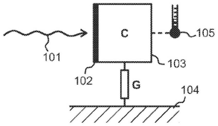
technical field [0001] The invention relates to the field of detection and measurement of electromagnetic energy at microwave frequencies. In particular, the present invention relates to an ultrasensitive detector structure and device capable of detecting extremely small amplitude microwave signals. Background technique [0002] Ultrasensitive detection methods of received electromagnetic radiation include calorimetry and bolometery. A calorimeter is a device in which the instantaneous rise in temperature of a detector element decays exponentially towards the temperature of a surrounding thermal bath. A bolometer has a detector element and a thermal bath, but the method measures power (energy over time), the average flux of incoming photons, rather than the precise energy of individual photons. [0003] Therefore, the schematic diagram of Figure 1 applies to both calorimeters and bolometers. The incident radiation 101 is absorbed in the absorber 102 such that the absorbed...

Claims


Application Information

Patent Timeline
Patent Type & Authority Patents(China)
IPC IPC(8): G01K11/00H01L39/22
CPCG01K11/006G01J2005/208H10N60/12G01K7/006G01K15/002G01K17/003G01R19/225G01R21/02G01R21/14H10N60/128G01J5/20
Inventor M·莫托滕R·科科尼米V·维斯特里宁R·拉克
Owner IQM FINLAND OY
Why Eureka
Try Eureka