Thermal conductivity coefficient measurement instrument for solid material
A measuring device and thermal conductivity technology, which is applied in the field of material thermal conductivity testing, can solve problems such as errors in the constant current measurement scheme of the theoretical system, and achieve good measurement and good thermal diffusivity effects
- Summary
- Abstract
- Description
- Claims
- Application Information
AI Technical Summary
Problems solved by technology
Method used
Image
Examples
Embodiment 1
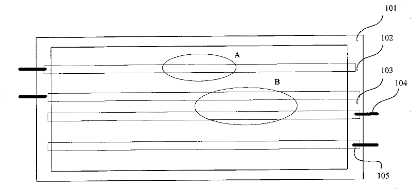
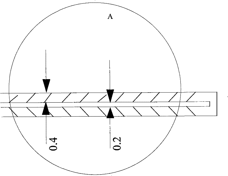
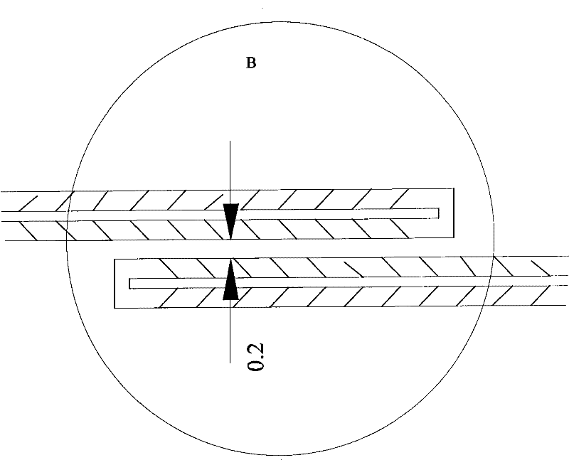
[0047] refer to figure 1 The top view of the structure of the heating chip of the present invention shown, figure 2 and image 3 gives figure 1 The schematic diagram of the enlarged structure of local area A and local area B in the middle and the size of the heating wire are marked in the figure, the unit in the figure is mm, and the material selected for the heating plate is a 20 μm thick pure nickel plate.
[0048] From figure 1 It can be seen from the figure that a solid material thermal conductivity measurement device of the present invention includes: a heating plate 101, and the heating plate 101 includes: a first heat band 102, a second heat band 103, and a third heat band 105 distributed side by side; The hot 102 band and the third hot band 105 respectively comprise a rectangular groove made of nickel material, and the second hot band 103 comprises two rectangular grooves (such as image 3 As shown), the rectangular groove is made of nickel material, the length is...
Embodiment 2
[0053] The measurement principle of the constant current source measurement device and the corresponding measurement device are described in detail below in conjunction with the accompanying drawings:
[0054] refer to figure 1 The schematic diagram of the structure of the heating plate of the present invention is shown. This embodiment uses a constant current method to provide energy to the heating plate, that is, in Figure 4 A constant current is loaded between points A and D of the shown Wheatstone bridge, and the structure of the measurement device for the thermal conductivity of the constant current source is as follows: Figure 5 As shown, it includes a constant current source 005 that provides energy for the heating chip 101, and the upper and lower surfaces of the heating chip 101 are respectively connected to the same material to be tested 004 and the material to be tested 002 (in this embodiment, the material to be tested 004 and the material to be tested are 002 i...
Embodiment 3
[0091] The measurement principle of the constant voltage source measurement device and the corresponding measurement device are described in detail below in conjunction with the accompanying drawings:
[0092] In this embodiment, a stable voltage is used to provide energy to the heating plate, so as to obtain another experimental measurement device and corresponding measurement principle for measuring thermal conductivity. The structure of the heating plate is as figure 1 as shown in Figure 7 As shown in the present invention, the load constant voltage source and the combined schematic diagram of the measurement device in the absolute measurement mode, this device is the same as the above-mentioned constant current source measurement device; when the constant current source loads the heating plate, as Figure 8 The equivalent circuit diagram shown is analyzed;
[0093]When the material to be tested is measured with a constant voltage source measuring device, the measurement...
PUM
| Property | Measurement | Unit |
|---|---|---|
| length | aaaaa | aaaaa |
| width | aaaaa | aaaaa |
| thermal conductivity | aaaaa | aaaaa |
Abstract
Description
Claims
Application Information
 - R&D
- Intellectual Property
- Life Sciences
- Materials
- Tech Scout
- Unparalleled Data Quality
- Higher Quality Content
- 60% Fewer Hallucinations
Browse by: Latest US Patents, China's latest patents, Technical Efficacy Thesaurus, Application Domain, Technology Topic, Popular Technical Reports.
© 2025 PatSnap. All rights reserved.Legal|Privacy policy|Modern Slavery Act Transparency Statement|Sitemap|About US| Contact US: help@patsnap.com


