Swinging concrete casting device for cement road laying
A road and cement technology, which is applied in the field of swinging concrete pouring devices for paving cement roads, can solve the problems of large equipment structure, high manufacturing cost, and large occupied area, and achieve the effects of strong flexibility, low manufacturing cost and compact structure
- Summary
- Abstract
- Description
- Claims
- Application Information
AI Technical Summary
Problems solved by technology
Method used
Image

Examples
Embodiment 1
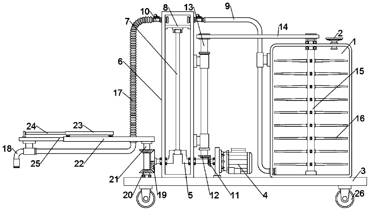
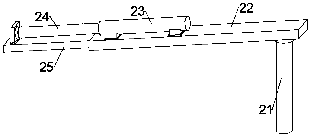
[0021] see Figure 1~3 , in an embodiment of the present invention, a swinging concrete pouring device for laying cement roads, comprising a bottom plate 3, a concrete mixing bucket 1 fixed above the rear of the bottom plate 3, a pumping mechanism for sucking concrete slurry and a connection pumping the oscillating assembly of the mechanism;
[0022] Specifically, the top of the concrete mixing bucket 1 is communicated with and fixed with an injection hopper 2, and the middle part of the bottom plate 3 is equipped with a drive motor 4 connected to a power supply and a switch with wires, and the drive motor 4 is connected to the pumping mechanism;
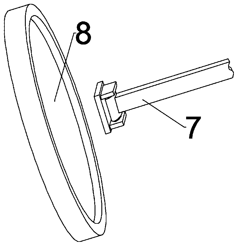
[0023] Further, the pumping mechanism includes a crankshaft 5 connected to the output end of the drive motor 4, a pump barrel 6 fixed on the bottom plate 3, a push plate 8 that is slidably connected to the inner wall of the pump barrel 6, and a push plate 8 connected to the crankshaft. 5, wherein the crankshaft 5 passes through the...
Embodiment 2
[0028] In order to prevent the concrete from standing still and solidifying in the concrete mixing tank 1 for a long time, in another embodiment of the present invention, a swinging concrete pouring device for cement road laying also includes a stirring mechanism, and the stirring mechanism includes a crankshaft connected by a bevel gear set. The driven shaft 13 of 5, the stirring shaft 15 connected to the driven shaft 13 through the transmission part 14, the stirring blade 16 fixed on the circumference of the stirring shaft 15; The stirring shaft 15 and the stirring blade 16 rotate to stir the concrete in the concrete mixing bucket 1 to prevent from solidification;
[0029] The bevel gear set includes a first bevel gear 11 fixed on the crankshaft 5, a second bevel gear 12 meshing with the first bevel gear 11 and fixed on the lower end of the driven shaft 13. It should be noted that the driven shaft 13 rotation is set on the side wall of the pump barrel 6, the stirring shaft 1...
PUM
 Abstract
Description
Claims
Application Information
 - Generate Ideas
- Intellectual Property
- Life Sciences
- Materials
- Tech Scout
- Unparalleled Data Quality
- Higher Quality Content
- 60% Fewer Hallucinations
Browse by: Latest US Patents, China's latest patents, Technical Efficacy Thesaurus, Application Domain, Technology Topic, Popular Technical Reports.
© 2025 PatSnap. All rights reserved.Legal|Privacy policy|Modern Slavery Act Transparency Statement|Sitemap|About US| Contact US: help@patsnap.com