
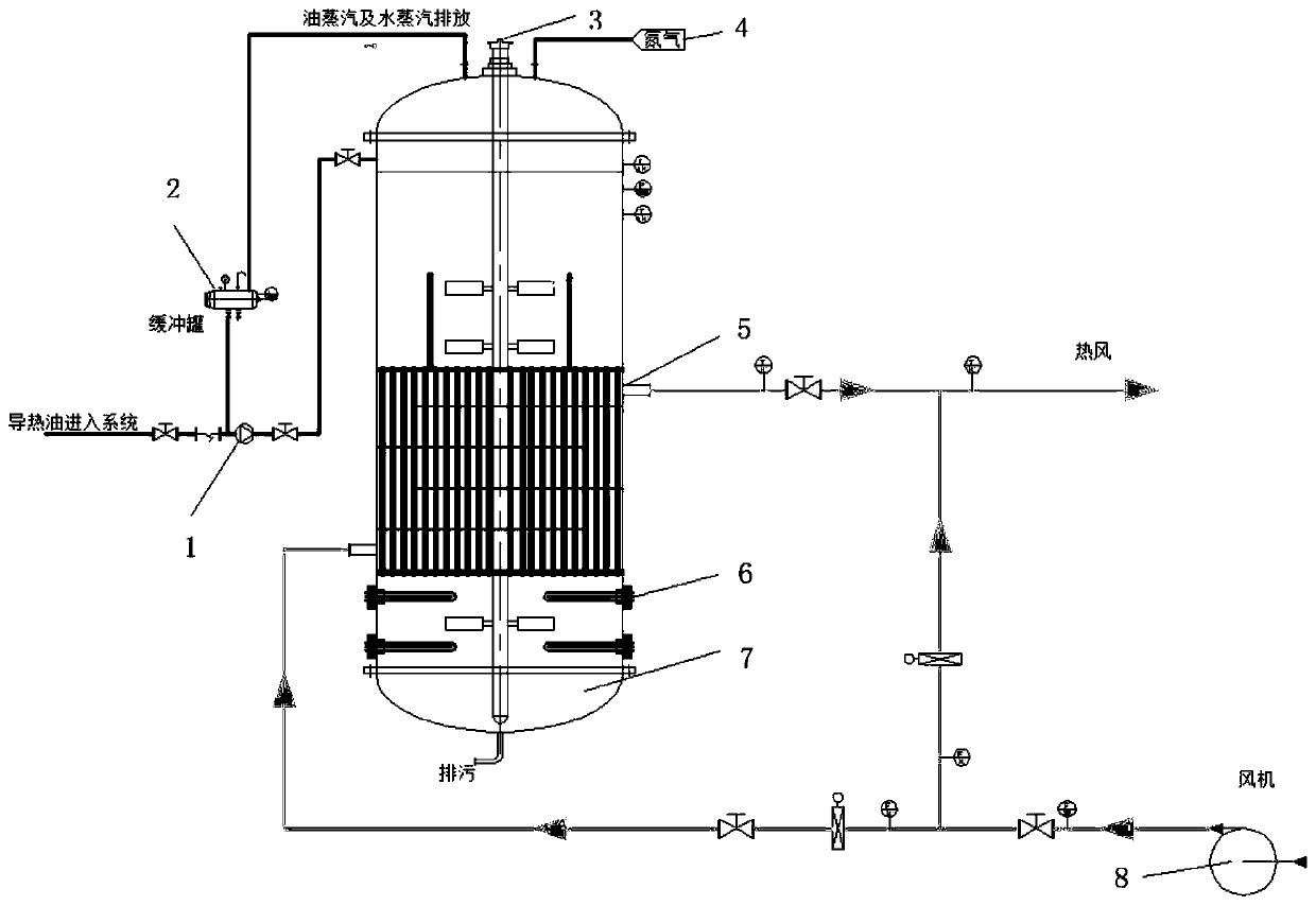
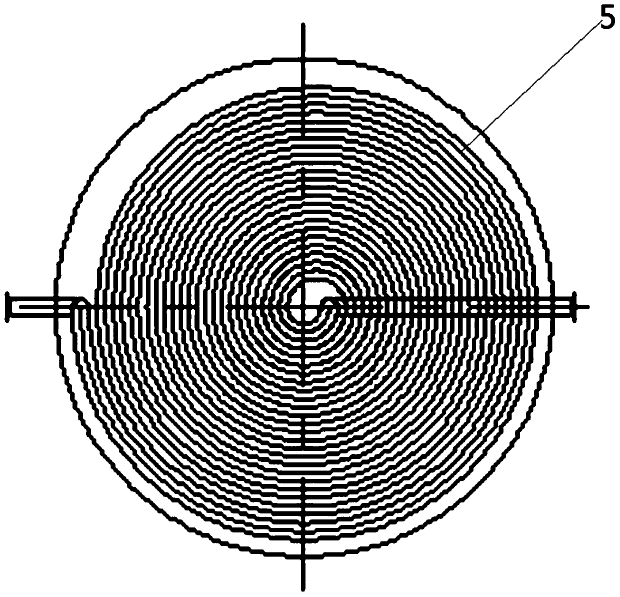
Integrated heat storage and heat supply system of heat-conduction oil furnace coupling spiral tube heat exchanger

The technology of a tube heat exchanger and a shell and tube heat exchanger is applied in the field of a heat transfer oil furnace coupled with a spiral tube heat exchanger integrated heat storage heat supply system, which can solve the problem of excessive peak-to-valley difference in power consumption, insufficient power, etc. Can not provide the heat exchange area to meet the needs of the work, to achieve the effect of reducing thermal resistance, improving production efficiency, and avoiding excessive local temperature

Inactive Publication Date: 2019-10-29
XI AN JIAOTONG UNIV
View PDF17 Cites 0 Cited by
  • Summary
  • Abstract
  • Description
  • Claims
  • Application Information

AI Technical Summary

Problems solved by technology

At present, there is a big power consumption problem: insufficient power during peak power consumption and excessive peak-to-valley difference
The type and structure of the heat exchanger at this stage cannot be well adapted to various working situations, and at the same time, it cannot provide a heat exchange area that meets the working needs in complex terrain

Method used


Image

  • Integrated heat storage and heat supply system of heat-conduction oil furnace coupling spiral tube heat exchanger
  • Integrated heat storage and heat supply system of heat-conduction oil furnace coupling spiral tube heat exchanger

Examples


Embodiment Construction

[0035] In describing the present invention, it should be understood that the terms "center", "longitudinal", "transverse", "upper", "lower", "front", "rear", "left", "right", " The orientation or positional relationship indicated by "vertical", "horizontal", "top", "bottom", "inner", "outer", "side", "end", "side" etc. is based on the Orientation or positional relationship is only for the convenience of describing the present invention and simplifying the description, and does not indicate or imply that the referred device or element must have a specific orientation, be constructed and operated in a specific orientation, and thus should not be construed as a limitation of the present invention. In addition, in the description of the present invention, unless otherwise specified, "plurality" means two or more.

[0036] In the description of the present invention, it should be noted that unless otherwise specified and limited, the terms "installation", "connection" and "connecti...


PUM


Abstract

The invention discloses an integrated heat storage and heat supply system of a heat-conduction oil furnace coupling spiral tube heat exchanger. The integrated heat storage and heat supply system comprises a heat-conduction oil heating and heat storage device, a heat supply device and a central processing unit, wherein the central processing unit is connected with the heat-conduction oil heating and heat storage device and the heat supply device, the heat-conduction oil heating and heat storage device comprises an oil storage tank, a shell-and-tube heat exchanger is arranged in the oil storagetank, the shell-and-tube heat exchanger is spirally arranged in heat-conducting oil and is connected with the heat supply system for carrying out heat exchange on heat storage medium in the oil storage tank so as to achieve stable control and output of the working condition of an outlet, and the central processing unit is used for realizing automatic control. According to the integrated heat storage and heat supply system, the heat of the heat-conduction oil heated in the electricity utilization valley period is released in other periods and air is heated to form hot air, so that the advantageof low off-peak electricity price can be effectively utilized, and stable control and output of hot air working condition of an outlet can be realized by utilizing an automatic control system.

Description

technical field [0001] The invention belongs to the technical field of heat supply, and in particular relates to an integrated heat storage heat supply system coupled with a heat conduction oil furnace coupled with a spiral tube heat exchanger. Background technique [0002] With the development of the national economy and the improvement of people's living standards, great changes have taken place in the structure of electricity consumption in my country, especially in coastal areas. At present, there is a big problem of electricity consumption: insufficient power during peak hours of electricity consumption and excessive peak-to-valley difference. In response to these problems, on the one hand, the power sector has accelerated the pace of power construction, and on the other hand, it has proposed a policy of "shaving peaks and filling valleys" to make full use of power resources. At present, power industry departments in various regions have announced power consumption pol...

Claims


Application Information

Patent Timeline
Patent Type & Authority Applications(China)
IPC IPC(8): F24D11/00F24D19/00F24D19/08F24D19/10F24H7/04F28F13/12
CPCF24D11/008F24D19/00F24D19/08F24D19/1084F24D19/1096F24H7/0416F28F13/12Y02B10/70Y02A30/60
Inventor 王树众赵军张宝权王涛崔成超蒋卓航李美全
Owner XI AN JIAOTONG UNIV
Learn More