Paper guiding unit, fixing device, and image formation device

A technology of guiding unit and paper, which is applied in the direction of electric recording process applying charge pattern, equipment of electric recording process applying charge pattern, electric recording technique, etc., can solve the problems of image scratching, poor conveying, inconvenient operation, etc.

Inactive Publication Date: 2019-10-29
KONICA MINOLTA TECH DEV WUXI
View PDF11 Cites 0 Cited by
  • Summary
  • Abstract
  • Description
  • Claims
  • Application Information

AI Technical Summary

Problems solved by technology

In this way, when the paper passes, the resistance increases, resulting in poor conveyance (such as paper jams, waves, image scratches, etc.)
[0004] In addition, in the prior art, the center of rotation R is also arranged near the end portion of the guide rail portion 611 on the downstream side in the paper conveying direction. However, this structure requires less operating space and is inconvenient to operate when handling paper jams. , and also exists Figure 18 and Figure 19 The above problems exist in the structure of

Method used


Image

  • Paper guiding unit, fixing device, and image formation device
  • Paper guiding unit, fixing device, and image formation device
  • Paper guiding unit, fixing device, and image formation device

Examples


no. 1 approach >

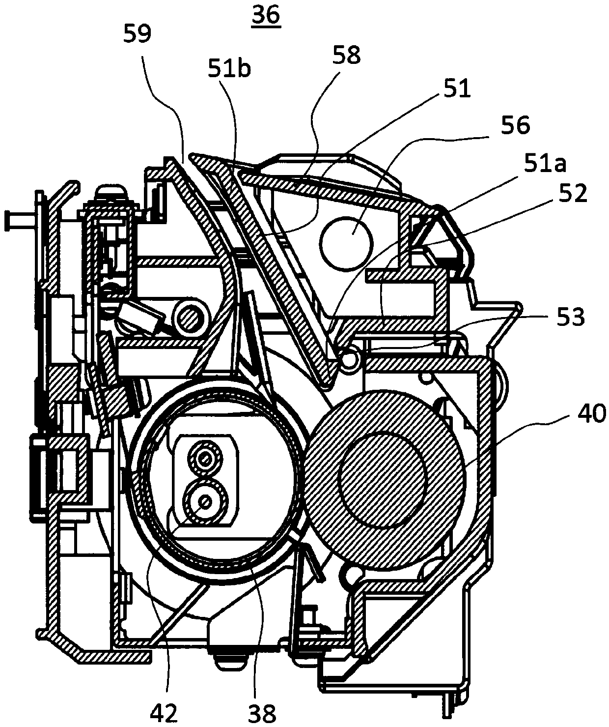
[0052] Below, refer to Figure 2 to Figure 5 A specific structure of the paper guide unit according to the first embodiment of the present invention will be described. image 3 It is a schematic diagram showing the paper guide unit according to the first embodiment of the present invention. Figure 4 It is a schematic perspective view showing the paper guide unit according to the first embodiment of the present invention. Figure 5 It is a schematic perspective view showing the paper guide unit according to the first embodiment of the present invention.

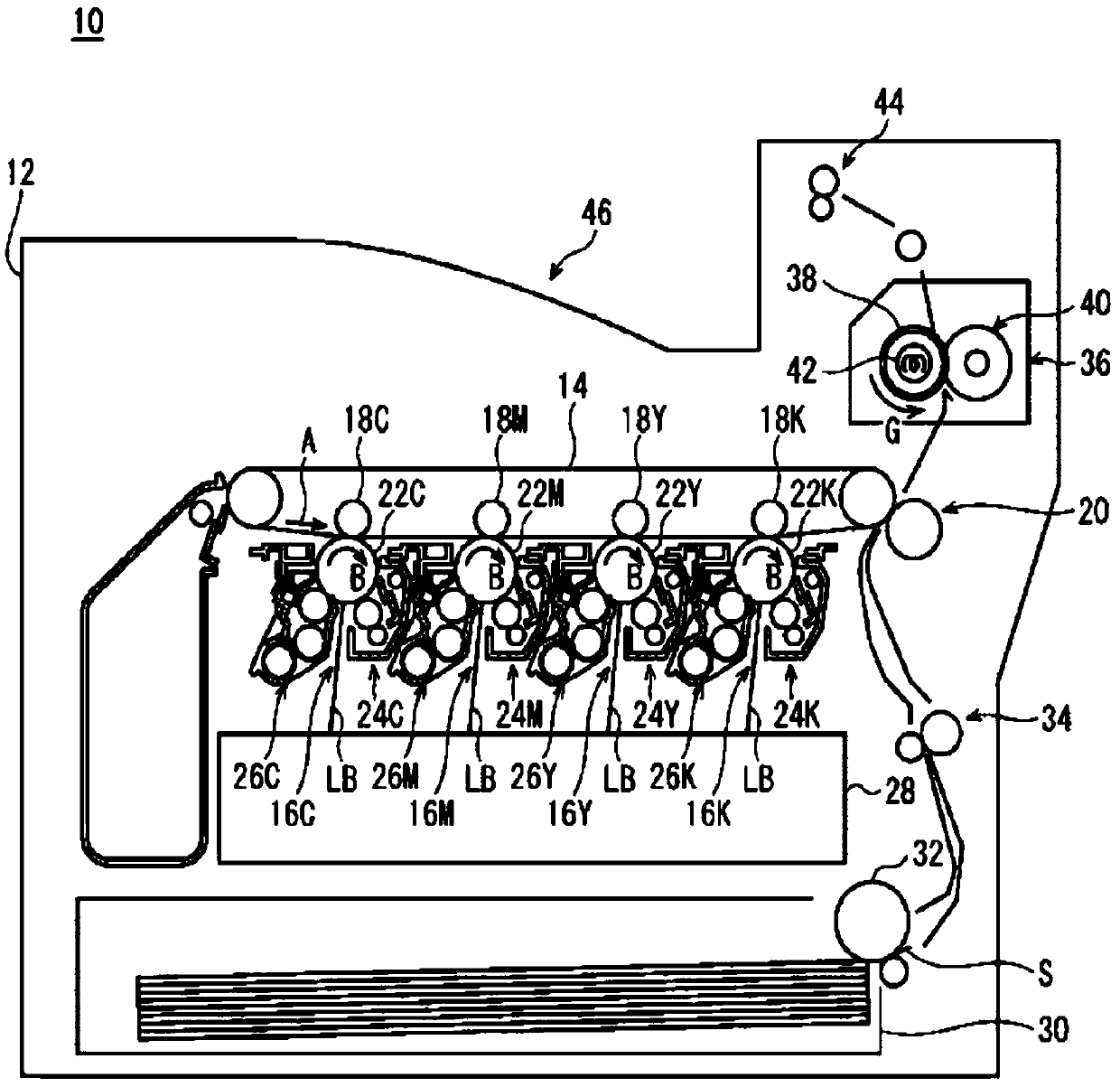
[0053] Such as Figure 2 to Figure 5 As shown, the fixing device 36 for fixing the transferred toner image on the paper includes: a fixing roller 38 arranged on the side of the fixing surface (the surface on which the toner image is formed) of the paper; The pressure roller 40 faces the fixing roller 38 on the (opposite surface to the fixing surface) side and sandwiches the paper conveyance path.

[0054] On the downstrea...

no. 2 approach >

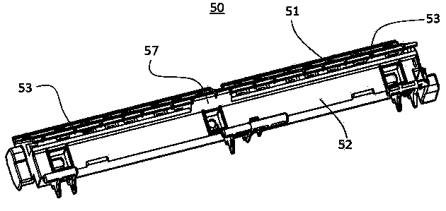
[0063] The difference between the second embodiment and the first embodiment is that the connection portion 57 between the rail portion 51 and the extension portion 52 is divided into multiple sections, in other words, one or more openings are provided on the connection portion 57 . Image 6 is a schematic diagram showing a case where the connecting portion is provided with one opening, Figure 7 It is a schematic diagram which shows the case where two openings are provided in the connection part. By dividing the connection portion 57 between the rail portion 51 and the extension portion 52 into multiple stages, the area of ​​the connection portion can be further reduced, and the end portion 51a of the extension portion 52 on the upstream side of the rail portion 51 in the sheet conveyance direction can be further reduced. The suppression of thermal expansion further suppresses the deformation of the rail portion 51 .

[0064] It should be noted that the shape and number of o...

no. 3 approach >

[0066] The guide rail part 51 and the extension part 52 can also be completely disconnected by the opening 53. In the case that the guide rail part 51 and the extension part 52 are completely disconnected by the opening 53, the guide rail part 51 and the extension part 52 can also be connected by a connecting part of other structures. Connected to be relatively movable.

[0067] E.g Figure 8 ~ Figure 12 As shown, the difference between the third embodiment and the first embodiment is that the guide rail part 51 and the extension part 52 are completely separated by the opening 53, and in addition, the extension part 52 and the guide rail for supporting the guide rail part 51 and the extension part 52 The portion support mechanism 58 is molded together by integral molding. Since integral molding is adopted, the cost can be reduced.

[0068] In addition, the guide rail portion 51 and the extension portion 52 are connected by a mounting mechanism as a connection portion, such a...


PUM


Abstract

The invention relates to a paper guiding unit, a fixing device, and an image formation device. The paper guiding unit is disposed on a downstream side of a paper conveying direction of a fixing part,is used for guiding paper that has been subjected to fixing and ensures a guiding gap when the paper is fed, and is provided with a guide rail part and an extension part, wherein the guide rail part extends along a paper conveying path and is used for guiding the paper that has been subjected to fixing, and the extension part is connected to an end portion of an upstream side of the paper conveying direction of the guide rail part, and is used for fixing the guide rail part to a guide rail portion supporting mechanism of the fixing device, and openings are disposed on both sides of a length direction between the guide rail part and the extension part. Therefore, the amount of thermal expansion of the entire guide rail part is uniform, deformation of the guide rail part is suppressed, and the guiding gap during paper feeding is ensured.

Description

technical field [0001] The present invention relates to a paper guide unit, a fixing device, and an image forming apparatus, and more particularly, to a paper guide unit, a fixing device, and an image forming device. Background technique [0002] In the existing technology, such as Figure 18 with Figure 19 As shown, an image forming apparatus is disclosed, which includes a paper guide unit including a guide rail portion 611 and an extension portion 612 . For reasons of strength and cost, the guide rail part 611 and the extension part 612 are integrally formed, and the integrated guide rail part 611 and the extension part 612 are connected with the guide rail part supporting mechanism 613 . Accordingly, the rail portion 611 , the extension portion 612 , and the rail portion support mechanism 613 can rotate around the rotation center R located below the rail portion support mechanism 613 . [0003] However, since the fixing part fixes the toner on the paper by heating and...

Claims


Application Information

Patent Timeline
Patent Type & Authority Applications(China)
IPC IPC(8): G03G15/00
CPCG03G15/6573
Inventor 陆晓祥吴洲
Owner KONICA MINOLTA TECH DEV WUXI
Why Eureka
Try Eureka