
Stamping die for part production

A technology for stamping dies and parts, applied in the direction of manufacturing tools, other manufacturing equipment/tools, etc., can solve the problems of affecting quality, easy bending, complicated operation, etc., to prevent copper plate damage, prevent copper plate offset, and improve stamping quality. Effect

Active Publication Date: 2019-11-01
唐山华舜科技股份有限公司
View PDF5 Cites 3 Cited by
  • Summary
  • Abstract
  • Description
  • Claims
  • Application Information

AI Technical Summary

Problems solved by technology

[0003] However, the thicker power lines in electrical equipment are connected by connecting pieces, and the connecting pieces of copper power lines are stamped by stamping dies, and then the thinner copper sheets are stamped to separate the connecting pieces from the copper plate. However, the copper plate The texture is soft, and it is easy to bend when placed inside the stamping die. When the copper plate is bent, the stamping quality of the power cord connection piece is affected. At the same time, the connection piece is under pressure during the stamping process, and it is easy to adhere to the stamping mold. On the one hand, it affects the quality of the next stamping. At the same time, the copper plate needs to be positioned during the stamping process. The operation is complicated. When the position of the copper plate is not placed accurately, it will affect the overall processing quality of the copper plate. At the same time, the stamped connecting pieces are not convenient for classification and storage. , the plate-shaped waste after stamping needs to be transported to other cutting devices for cutting, the processing procedure is cumbersome, and it is not easy to transport

Method used


Image

  • Stamping die for part production
  • Stamping die for part production
  • Stamping die for part production

Examples


Embodiment Construction

[0030] In order to make the technical means, creative features, goals and effects achieved by the present invention easy to understand, the present invention will be further elaborated below in conjunction with specific embodiments.

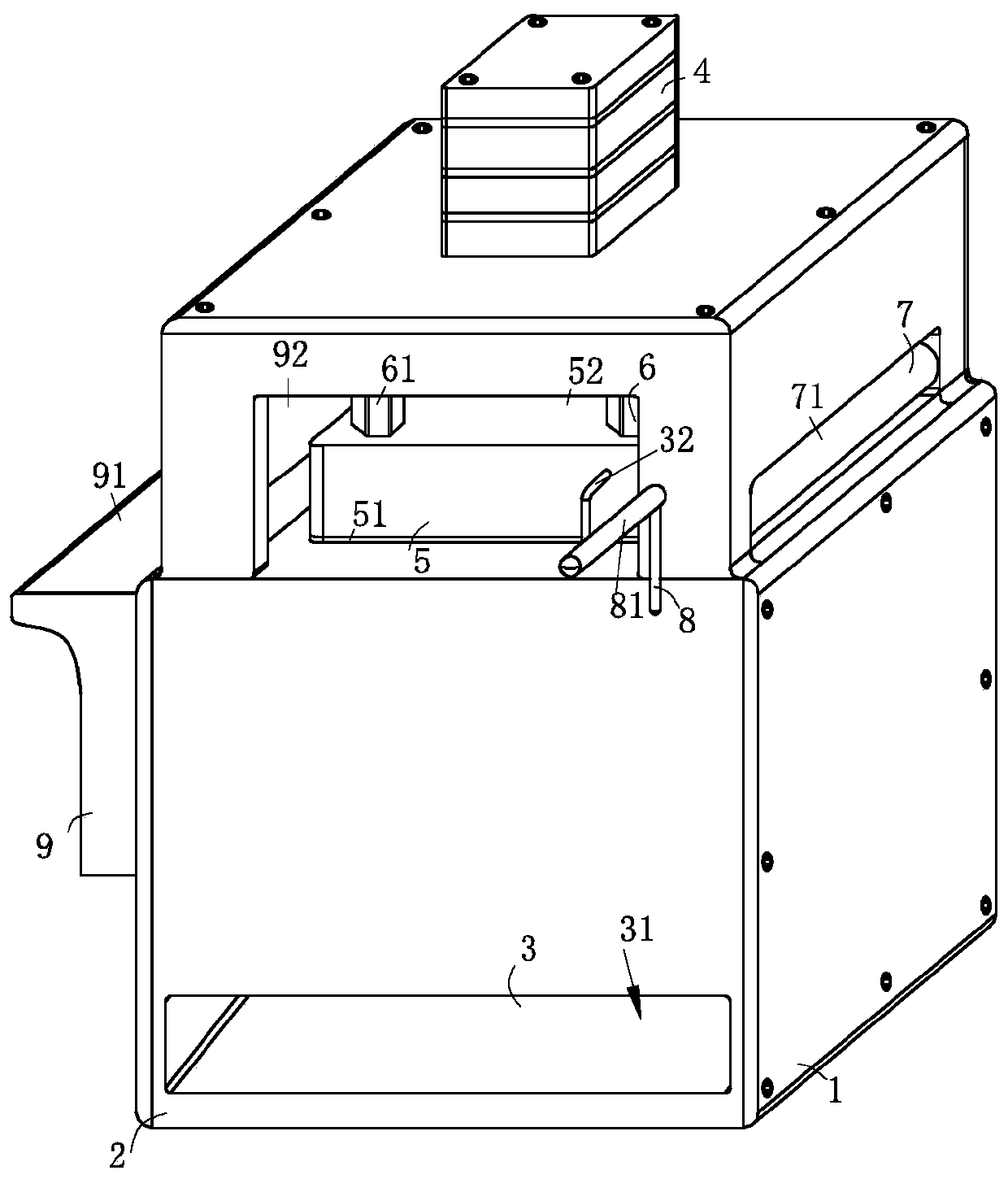
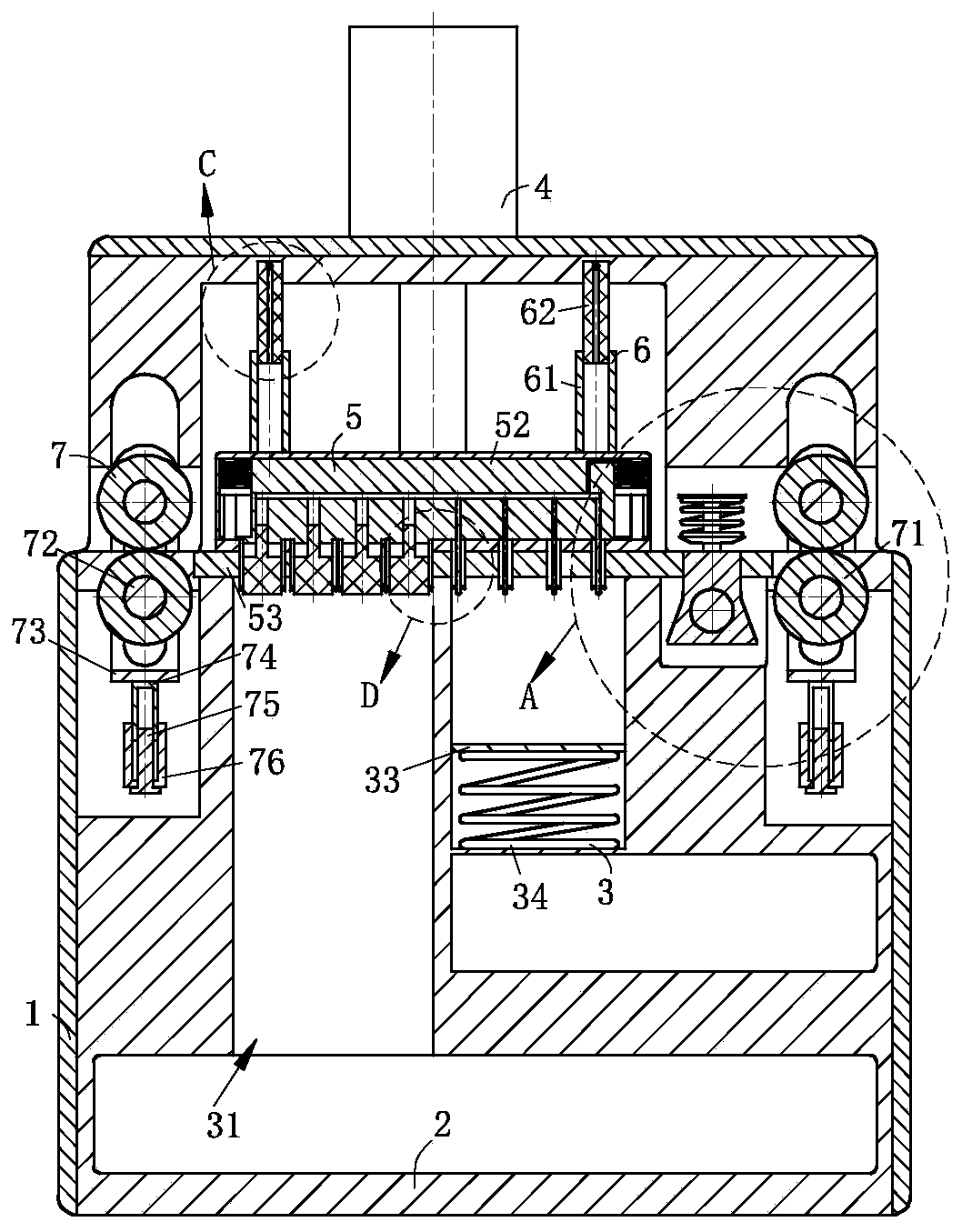
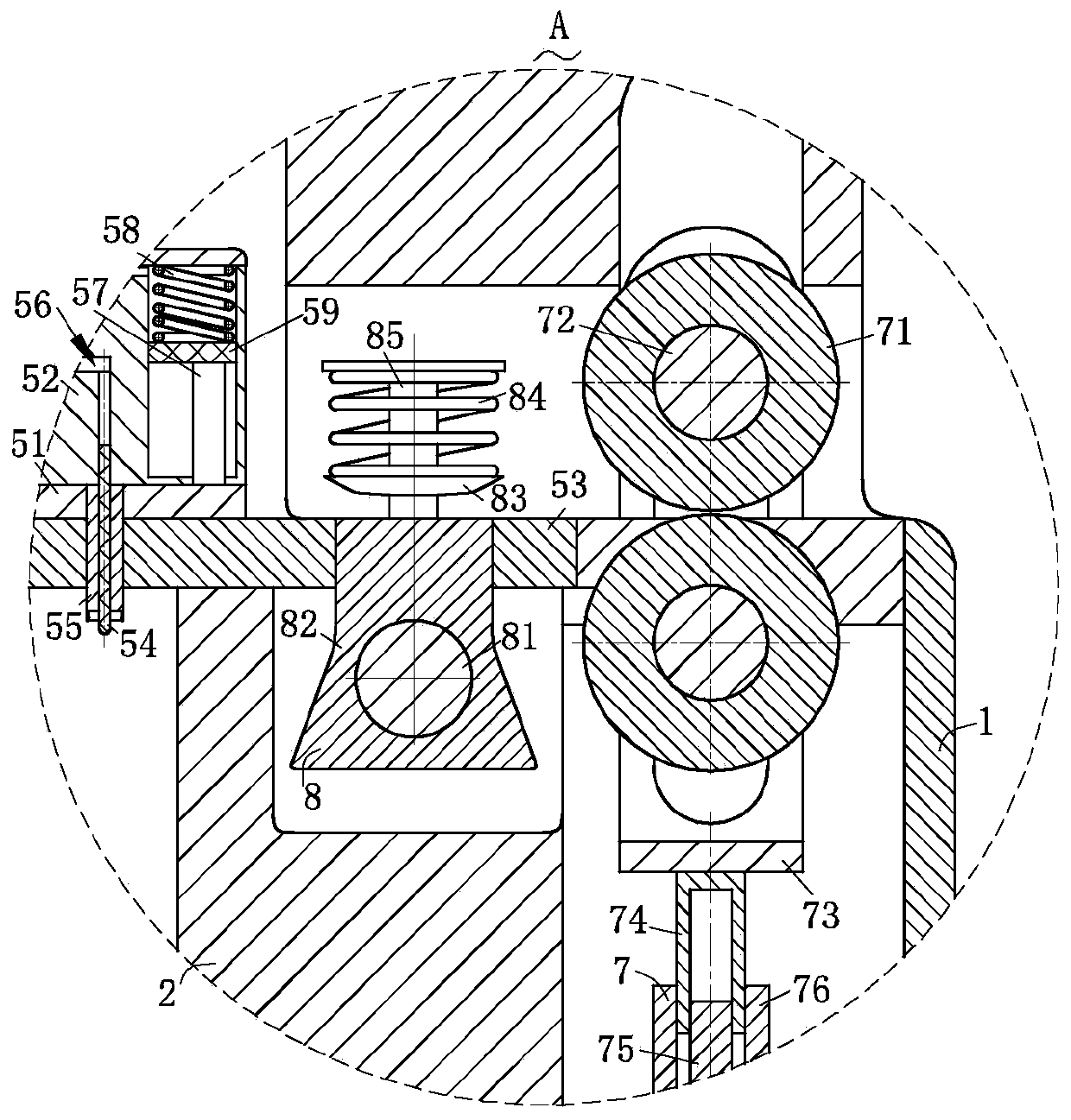
[0031] Such as Figure 1-Figure 8 As shown, a stamping die for parts production according to the present invention includes a plurality of access panels 1, a shell 2, a blanking structure 3, an electric hydraulic cylinder 4, a stamping structure 5, a transmission structure 6, a flattening structure 7, a guide structure 8 and cutting structure 9; the housing 2 is provided with a plurality of access panels 1 for overhauling internal components, and the access panels 1 of rectangular structure are connected with the housing 2 by bolts; the housing 2 The top end is provided with the electric hydraulic cylinder 4 for providing power, and the electric hydraulic cylinder 4 is detachably connected to the shell 2; structure 5, and the stamping structure ...


PUM


Abstract

The invention relates to the field of stamping dies for part production, in particular to a stamping die for part production. The stamping die comprises a plurality of maintenance plates, a shell, a discharging structure, an electric hydraulic cylinder, a stamping structure, a transmission structure, a rolling-out structure, a guide structure and a cutting structure. The stamping structure is connected to the electric hydraulic cylinder, then the stamping structure can be driven through the electric hydraulic cylinder to stamp on copper plates step by step conveniently, then the situation thatcopper plates are damaged in the stamping process is effectively prevented, meanwhile, after the stamping structure finishes stamping, stamped parts are driven through extrusion force to be separatedfrom the stamping structure conveniently, and then the stamping quality and the stamping efficiency are greatly improved; the rolling-out structure is arranged inside the shell, then the copper plates can be rolled out through the rolling-out structure conveniently, meanwhile, the transmission structure is connected to the rolling-out structure, and then rolling and stamping are synchronous; andthe guide structure is fixed on the shell, then the copper plates with different thicknesses and different widths can be guided conveniently, and the situation that the copper plates shift, so that the production and machining quality of the copper plates is influenced is avoided.

Description

technical field [0001] The invention relates to the field of stamping dies for parts production, in particular to a stamping die for parts production. Background technique [0002] Stamping die is a special process equipment for processing materials (metal or non-metal) into parts (or semi-finished products) in cold stamping processing. It is called cold stamping die (commonly known as cold stamping die). Stamping is at room temperature. A pressure processing method in which the mold installed on the press applies pressure to the material to cause separation or plastic deformation to obtain the required parts. [0003] However, the thicker power lines in electrical equipment are connected by connecting pieces, and the copper power line connecting pieces are stamped by stamping dies, and then the thinner copper sheets are stamped to separate the connecting pieces from the copper plate. However, the copper plate The texture is soft, and it is easy to bend when it is placed in...

Claims


Application Information

Patent Timeline
IPC IPC(8): B21D35/00B21D22/02B21D1/02B23P23/04
CPCB21D1/02B21D22/02B21D35/002B23P23/04
Inventor 不公告发明人
Owner 唐山华舜科技股份有限公司
Learn More