Automatic assembly production line for fan impellers

An automatic assembly, fan impeller technology, applied in the direction of assembly machine, feeding device, positioning device, etc., can solve the problems of low processing efficiency, high labor cost, poor product processing consistency, etc.

Active Publication Date: 2019-11-01
FOSHAN NANHAI GUANGDONG TECH UNIV CNC EQUIP COOP INNOVATION INST +1
View PDF9 Cites 7 Cited by
  • Summary
  • Abstract
  • Description
  • Claims
  • Application Information

AI Technical Summary

Problems solved by technology

In the existing technology, the assembly of the fan impeller is to manually feed the stamped blades to the upper end cover, then manually feed the shaft head and the upper end cover pressing material of the stamped blades, and finally manually assemble the lower end cover pressing material, all manual operation, High labor costs, low product processing efficiency, and poor product processing consistency

Method used


Image

  • Automatic assembly production line for fan impellers
  • Automatic assembly production line for fan impellers
  • Automatic assembly production line for fan impellers

Examples


Embodiment 1

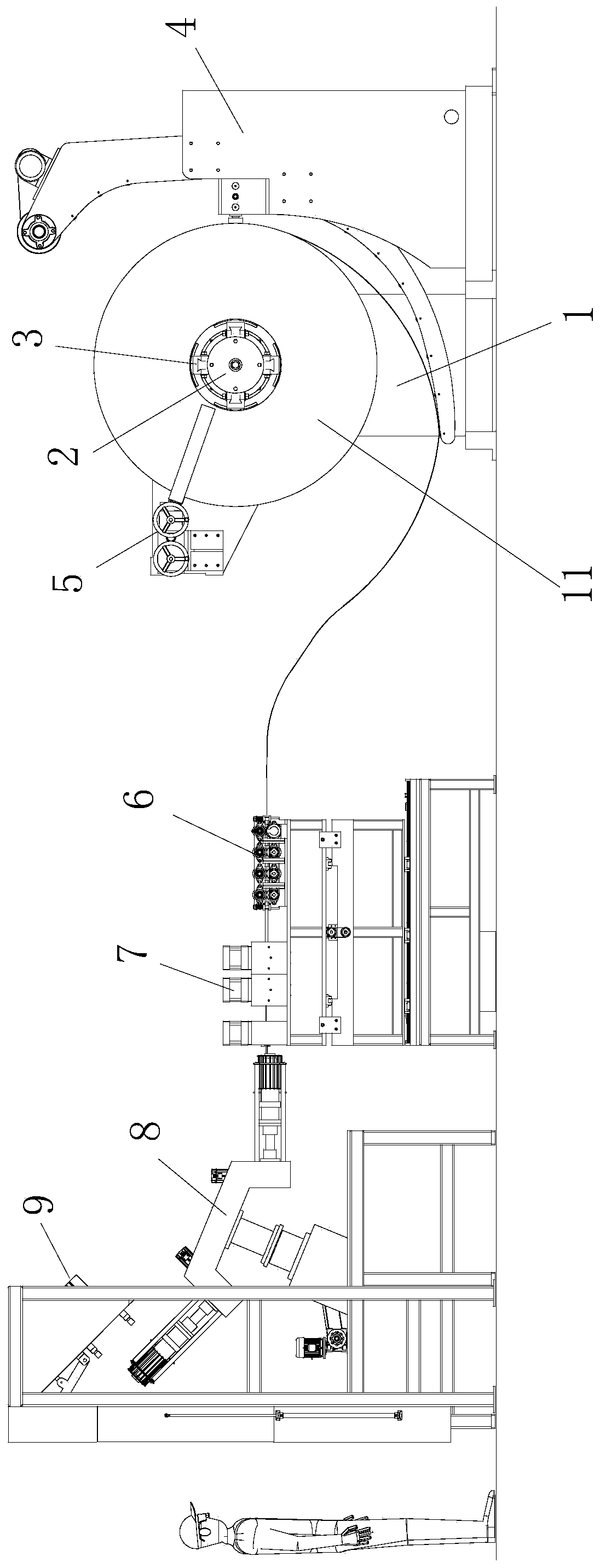
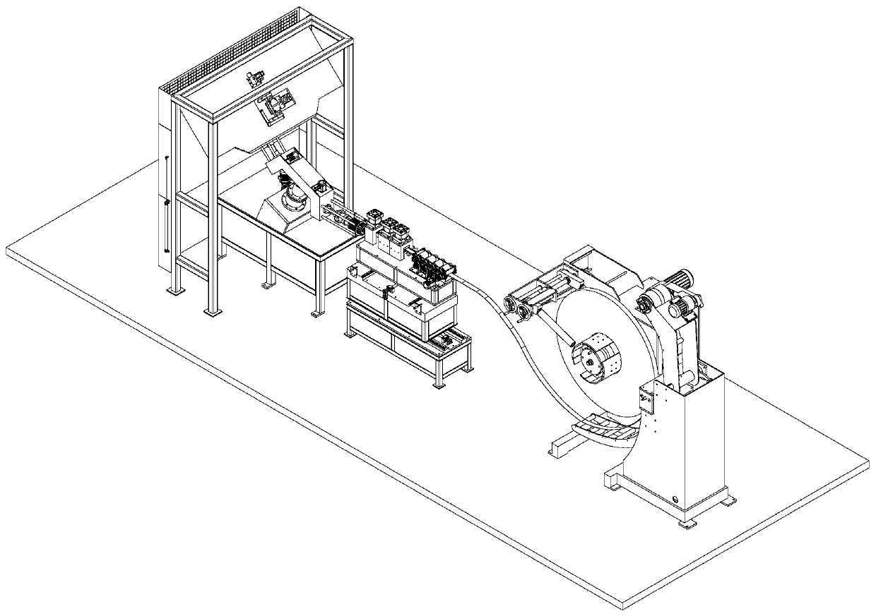
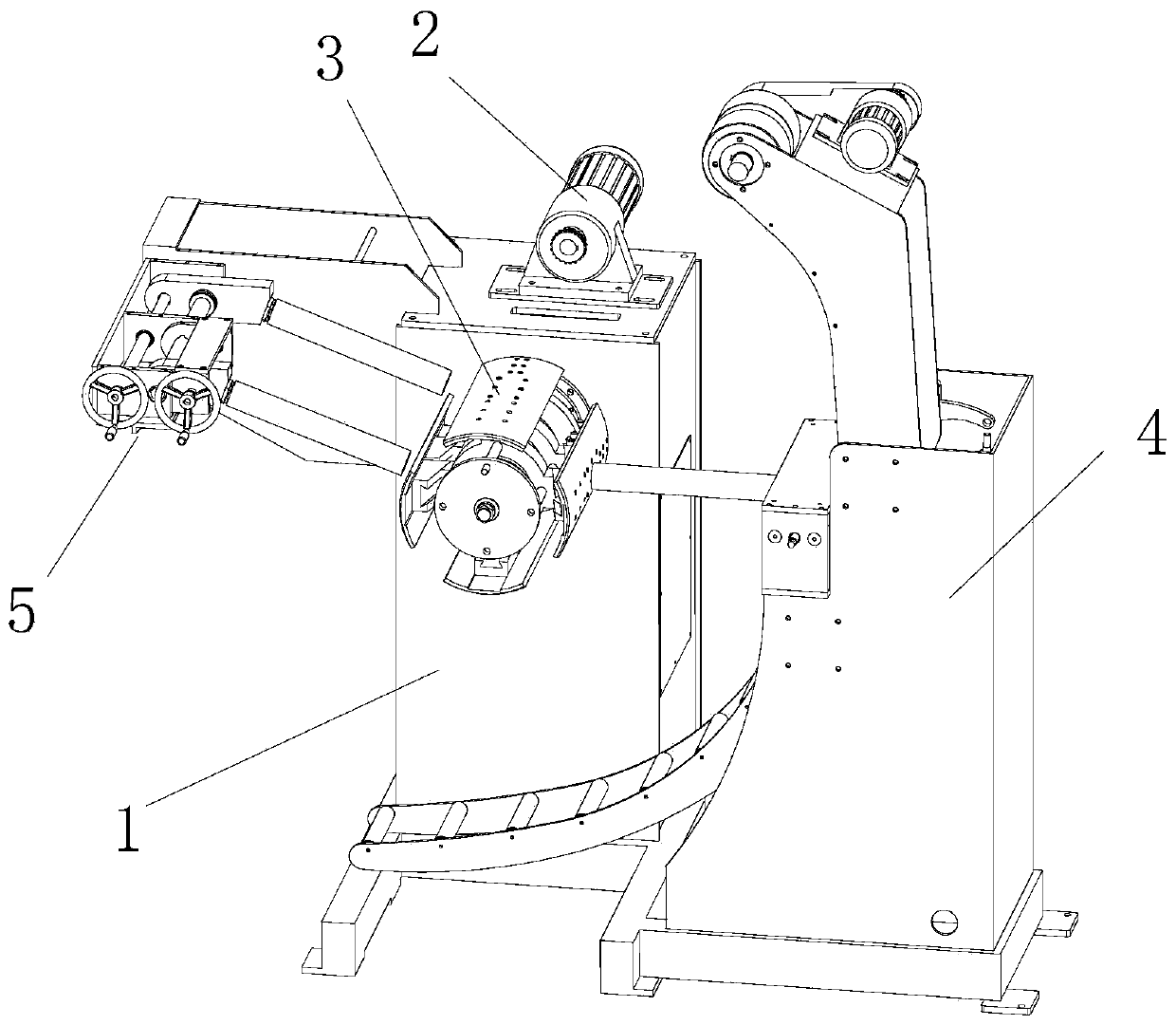
[0084] like figure 1 and figure 2 As shown in the figure, this embodiment discloses an automatic assembly production line for fan impellers. The assembly production line mainly includes a steel strip uncoiling mechanism, a blade roll forming feeding mechanism 6, a blade punching mechanism 7, and a double-station rotary assembly mechanism. 8, and the material pressing and unloading mechanism 9. The worker puts the steel strip coil material into the steel strip uncoiling mechanism, and the steel strip head extends into the blade roll forming feeding mechanism 6 . The rolled steel strip is sent into the blade blanking mechanism 7 for blanking and cutting. After being punched into a blade, it enters the double-station rotary assembly mechanism 8 for positioning and assembly together with the upper and lower end caps. The double-station rotary assembly mechanism 8 sends the blades and the upper and lower end caps to the material pressing and unloading mechanism 9 for positionin...


PUM


Abstract

The invention discloses an automatic assembly production line for fan impellers. The automatic assembly production line for the fan impellers comprises a steel belt uncoiling mechanism, a blade roll forming feeding mechanism, a blade blanking mechanism, a double-station rotary assembly mechanism and a material pressing feeding and discharging mechanism sequentially arranged. During production, a lower end cover is manually fed from a material pressing feeding and discharging mechanism; a pneumatic safety door is closed, a double-station rotating assembly device rotates to rotate a machined finished product out, and the machined finished product is transferred to a de-stamping assembly blade; the steel belt uncoiling mechanism at the front end uncoils and feeds the machined finished product; a steel belt is pressed and formed through a straightening roller, then the steel belt is stamped and cut into a blade, and the blade is stamped and assembled into the lower end cover by matching with servo feeding and blanking cutting; the blade is transferred out by rotating through the double-station rotary assembly; the pneumatic safety door is opened, and an upper end cover is manually fed;the pneumatic safety door is closed, an open-close clamping pinch roller mechanism and a centering pressure head on a rotating pinch are matched with a shaft of the rotary assembly mechanism to rotate, and spinning fixation of the blade and the upper end cover and the lower end cover is completed; and the safety door is opened, finished products are manually discharged, and the lower end cover isfed.

Description

technical field [0001] The invention relates to the field of industrial automatic production lines, in particular to an automatic assembly production line for fan impellers. Background technique [0002] At present, the impeller is the main working part of the fan, which plays a decisive role in the stability and life of the fan. It is mainly composed of the upper end cover, the shaft core, the blades and the lower end cover. The blades are distributed along the circumference of the upper end cover, and the shaft core and the upper end cover are riveted. connection, the lower end of the blade is connected with the lower end cover. In the prior art, the fan impeller is assembled by manually feeding the punching blade to the upper end cover, then manually feeding the shaft head and pressing the upper end cover of the stamped blade, and finally manually assembling the lower end cover and pressing the material, which is all manual operation. The labor cost is high, the product ...

Claims


Application Information

Patent Timeline
Patent Type & Authority Applications(China)
IPC IPC(8): B23P21/00B23P19/00B21D53/78B21D43/02B21D39/00B21D35/00B21D28/14B21D28/02B21D22/02B21C47/30B21C47/18
CPCB21C47/18B21C47/30B21D22/02B21D28/02B21D28/14B21D35/002B21D39/00B21D43/02B21D53/78B23P19/001B23P21/004
Inventor 袁燕饶俊伟
Owner FOSHAN NANHAI GUANGDONG TECH UNIV CNC EQUIP COOP INNOVATION INST
Why Eureka
Try Eureka