Angle grinder positioning tool

A technology for positioning tooling and angle grinders. It is applied in the direction of grinding/polishing safety devices, grinding machines, manufacturing tools, etc. It can solve the problems of low cutting efficiency and low cutting precision, and achieve the purpose of increasing cutting speed, solving overwork and reducing force. Effect

Active Publication Date: 2019-11-01
双一科技盐城有限公司
View PDF5 Cites 3 Cited by
  • Summary
  • Abstract
  • Description
  • Claims
  • Application Information

AI Technical Summary

Problems solved by technology

[0003] In view of the shortcomings of the prior art described above, the purpose of the present invention is to provide a positioning tool for angle grinders, which is used to solve the problems of low cutting accuracy and low cutting efficiency of angle grinders in the prior art

Method used


Image

  • Angle grinder positioning tool
  • Angle grinder positioning tool

Examples


Embodiment 1

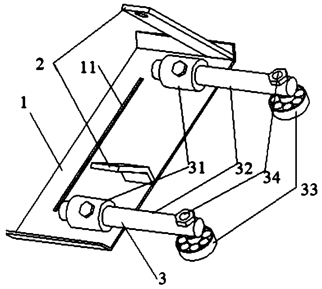
[0029] see figure 1 , the present invention provides a positioning tool for an angle grinder, comprising a guide plate 1, a mounting bracket 2 fixedly connected to the guide plate 1 and a positioning device 3 fixed on the guide plate 1, the guide plate 1 is provided with a Parallel to the cutting grooves 11 , the upper end of the mounting bracket 2 is provided with a connection hole, and the installation direction of the positioning device 3 is perpendicular to the direction of the cutting edge 11 . The positioning tool is used in conjunction with the angle grinder. There is a connecting hole on both sides of the angle grinder body, which is placed on the guide plate 1. The cutting blade installed on the angle grinder is stuck in the cutting groove 11 on the guide plate. The body is fixedly connected together with the connecting hole on the upper end of the mounting bracket 2 through screws. In this embodiment, the mounting bracket 2 includes two, and the angle grinder body is...

Embodiment 2

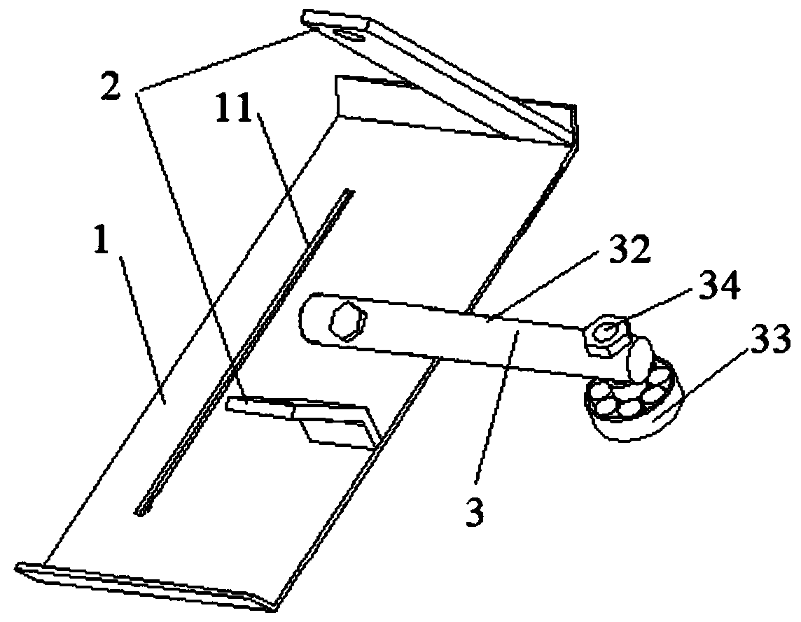
[0033] refer to figure 2 The difference between this embodiment and the first embodiment is that a set of positioning devices 3 is used, and the positioning sleeve 31 in the first embodiment is removed, so that the positioning rod 32 is directly connected to the guide plate. In this embodiment, the direction of the positioning device 3 is perpendicular to the direction of the cutting groove 11, and is located in the middle of the guide plate 1. One end of the positioning rod 32 is directly fixed on the guide plate 1. If welding is used, it is connected with the positioning roller 33. One end is provided with a plurality of screw holes, and the middle of the positioning roller 34 is provided with screw holes, and the two ends of the positioning connecting rod 34 are provided with threads. Screw holes, fixed with nuts. By adjusting the connection position between the positioning rod 32 and the positioning roller 33, the distance from which the positioning rod 32 protrudes from...


PUM


Abstract

The invention provides an angle grinder positioning tool. The tool comprises a guide plate, mounting supports fixedly connected with the guide plate, and positioning devices fixed to the guide plate.The positioning devices comprise positioning rods connected with the guide plate and positioning rollers connected with the positioning rods. During use, an angle grinder is fixed to the positioning tool, the guide plate of the positioning tool makes contact with the product surface, the positioning rollers are attached to the outer edge of the product, and through adjusting the connecting position of the positioning rods and the guide plate or the connecting position of the positioning rods and the positioning rollers, the cutting size is adjusted. Through the angle grinder positioning tool,labor intensity of a worker is reduced, cutting efficiency is improved, and the product cutting quality is ensured.

Description

technical field [0001] The invention relates to the field of mechanical processing, in particular to a positioning tool for an angle grinder. Background technique [0002] Composite material products are mostly injection molded. Usually after injection molding, the edges of the product are uneven and need to be cut with an angle grinder to meet the use standard. At present, the hand-held angle grinder is commonly used, that is, the manual hand-held angle grinder cuts according to the cutting line on the outer surface of the product. The operation effect has a lot to do with the experience and proficiency of the worker's master. Moreover, some injection molding products such as cabin covers are relatively large in size, and the cutting size is usually large. The operator holds the device for a long time, causing arm fatigue and easy shaking. A little carelessness during cutting can cut the product small or large. If it is cut too large, it needs to be cut again, if it is cut...

Claims


Application Information

Patent Timeline
Patent Type & Authority Applications(China)
IPC IPC(8): B24B23/02B24B55/00
CPCB24B23/028B24B55/00
Inventor 冯广瑞崔海军王庆华
Owner 双一科技盐城有限公司
Why Eureka
Try Eureka