Optical fiber cable high-precision clip buckle

A technology of optical fiber cable and high-precision clamping, which is applied in the direction of optical fiber/cable installation, workpiece clamping device, manufacturing tools, etc. It can solve the problems of easy loosening, inability to clamp optical fiber cables, and low clamping accuracy of clamping buckles, etc., to achieve Ingenious design, easy installation and removal

Active Publication Date: 2021-04-06
NINGBO ZHENGYU FASTENERS
View PDF6 Cites 0 Cited by
  • Summary
  • Abstract
  • Description
  • Claims
  • Application Information

AI Technical Summary

Problems solved by technology

[0004] The purpose of the present invention is to provide a high-precision clamping buckle for optical fiber cables. The optical fiber cables are clamped and fixed by four first clamping plates, and each first clamping plate can move flexibly to clamp and fix optical fiber cables of different sizes. The first lead screw and the second lead screw are used together to control each first clamping plate with high precision, which solves the technical problems of low clamping precision and easy loosening of the existing optical fiber cable clamping buckle;
[0007] By installing the second clamping piece on the first clamping piece, and clamping the optical fiber cable through the second clamping plate, the optical fiber cable perpendicular to the axial direction of the slot can be installed, and the second clamping piece and The first clamping part is more convenient to install and disassemble, and the design is ingenious, which solves the technical problem that the existing optical fiber cable clamping buckle cannot clamp the optical fiber cables in different directions after being fixed.

Method used


Image

  • Optical fiber cable high-precision clip buckle
  • Optical fiber cable high-precision clip buckle
  • Optical fiber cable high-precision clip buckle

Examples


Embodiment Construction

[0040] The technical solutions of the present invention will be clearly and completely described below in conjunction with the embodiments. Apparently, the described embodiments are only some of the embodiments of the present invention, not all of them. Based on the embodiments of the present invention, all other embodiments obtained by persons of ordinary skill in the art without creative efforts fall within the protection scope of the present invention.

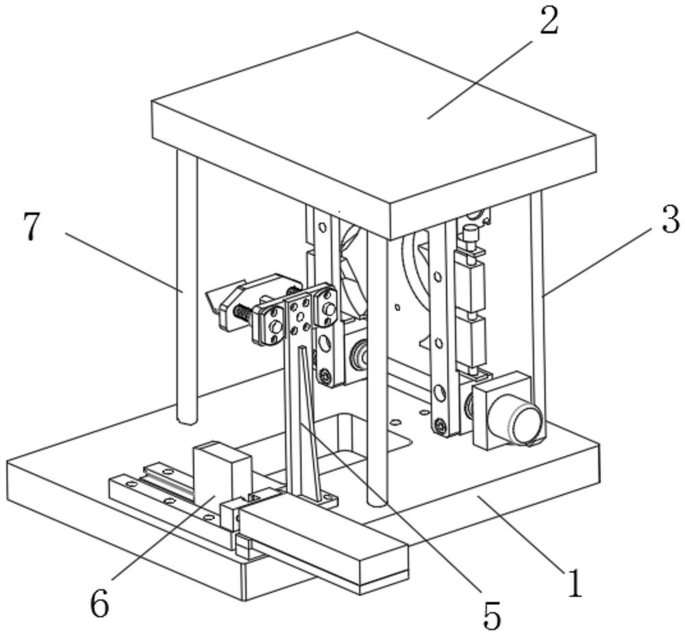
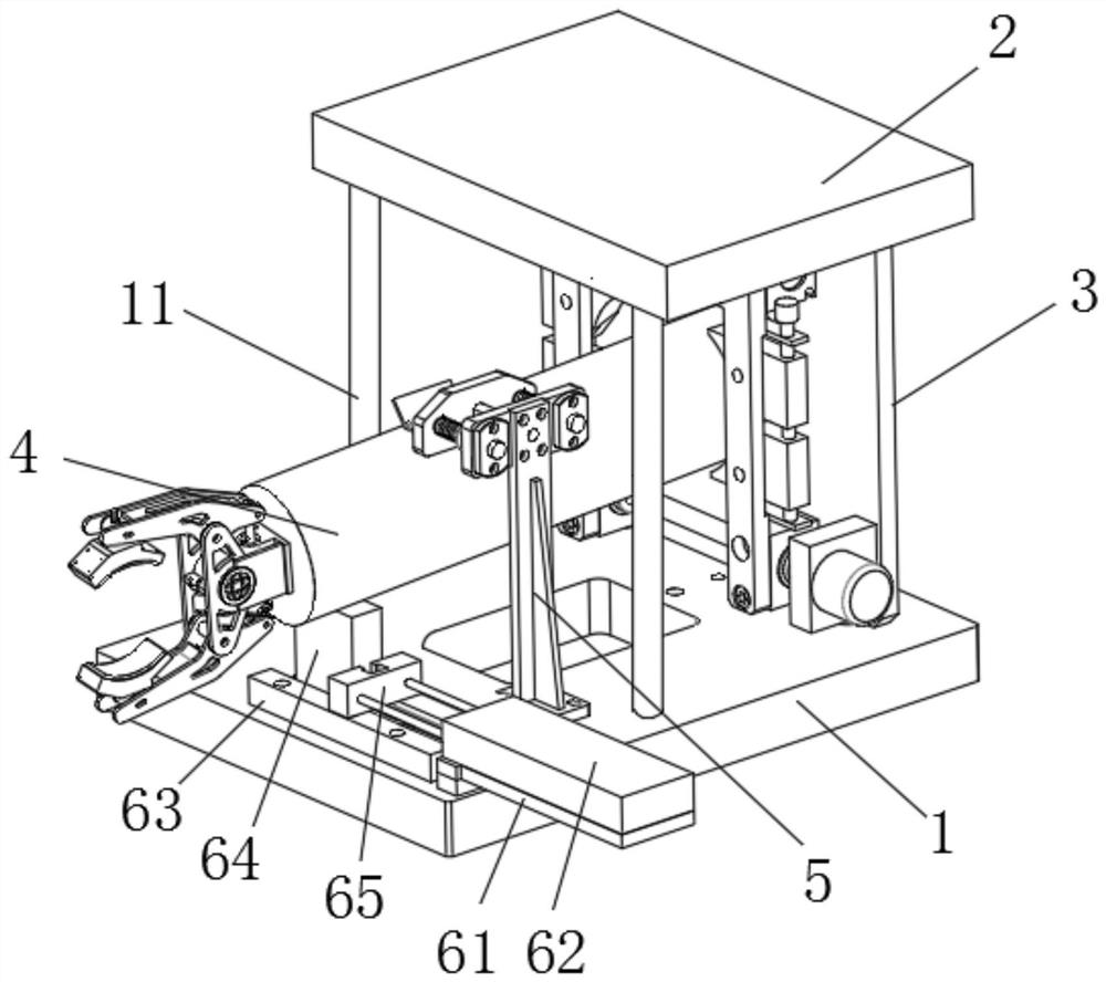
[0041] Such as Figure 1-7 As shown, the fiber optic cable high-precision clamping buckle includes a bottom plate 1 and a top plate 2, a first clamping member 3 is arranged between the bottom plate 1 and the top plate 2, and two vertically fixed between the bottom plate 1 and the top plate 2 support rod 7;

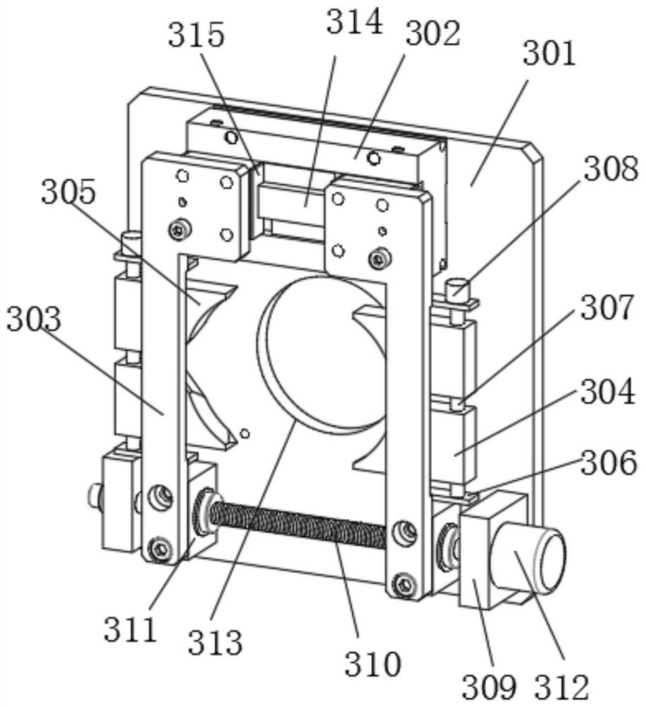
[0042] The first clamping member 3 includes a mounting plate 301, the mounting plate 301 is vertically arranged, the middle part of the mounting plate 301 is provided with a through groove 313, the bottom surface of th...


PUM


Abstract

The invention discloses a high-precision clamping buckle for an optical fiber cable. There is a second clamping piece between the bottom plate and the top plate, and one end of the connecting column is clamped by four first clamping plates; each first clamping plate is easy to move, and can clamp and fix optical fiber cables of different sizes , each first clamping plate is controlled by the first lead screw and the second lead screw, with high precision and good clamping effect; the clamping buckle can meet different installation environments and has strong applicability; rotate the first clamping plate The second clamping plate and the second clamping plate are easy to disassemble and can meet the installation of optical fiber cables of different specifications; the second clamping part and the first clamping part are more convenient to install and disassemble, and the design is ingenious. The clamping buckle can be applied to For the clamping of fiber optic cables in different directions.

Description

technical field [0001] The invention relates to the technical field of optical fiber cable clips, in particular to high-precision optical fiber cable clips. Background technique [0002] With the continuous development of society, the laying of fiber optic cables is becoming more and more common. Fiber optic cables are communication cables consisting of two or more glass or plastic optical The PVC outer casing is covered, and the signal transmission along the inner optical fiber generally uses infrared rays, and the optical fiber cable needs to be fastened and fixed with a clip buckle during installation; [0003] The patent document (CN200949709Y) discloses a clip structure for cable joints or hoses. After the cables pass through the cable joints and the hoses, the software is placed in the placement space formed between the two clamping arms of the base. After the buckle arm is buckled with the second clamp arm, the positioning pieces on the first and second inner linings...

Claims


Application Information

Patent Timeline
Patent Type & Authority Patents(China)
IPC IPC(8): B25B11/00G02B6/46
CPCB25B11/00G02B6/46
Inventor 李博恩
Owner NINGBO ZHENGYU FASTENERS
Why Eureka
Try Eureka