
Automobile part drying device

A drying device and auto parts technology, applied in the field of auto parts, can solve problems such as waste of resources, errors, and affecting the quality of parts production, and achieve the effects of preventing waste, good drying effect, and high degree of automation

Active Publication Date: 2019-11-01
萍乡粤科技术服务中心
View PDF7 Cites 2 Cited by
  • Summary
  • Abstract
  • Description
  • Claims
  • Application Information

AI Technical Summary

Problems solved by technology

[0002] In modern society, automobiles provide great convenience for people's travel, and the automobile industry has also developed greatly. Among them, auto parts are the foundation of the automobile industry and a necessary factor for the sustainable and healthy development of the automobile industry. Independent innovation of parts It also has a strong driving force for the development of the vehicle industry. If the processing of parts is not emphasized, the quality of the vehicle cannot be further improved. The existing drying devices used in the processing of auto parts often fail to achieve a good quality. The drying effect can easily lead to uneven drying on the surface of the parts, which affects the production quality of the parts. Sometimes in order to ensure the drying quality, the parts are over-dried, resulting in a waste of resources, and the drying of the parts requires workers to check. Human factors may cause errors while increasing the workload of employees

Method used


Image

  • Automobile part drying device
  • Automobile part drying device
  • Automobile part drying device

Examples


Embodiment Construction

[0018] The following will clearly and completely describe the technical solutions in the embodiments of the present invention with reference to the accompanying drawings in the embodiments of the present invention. Obviously, the described embodiments are only some, not all, embodiments of the present invention.

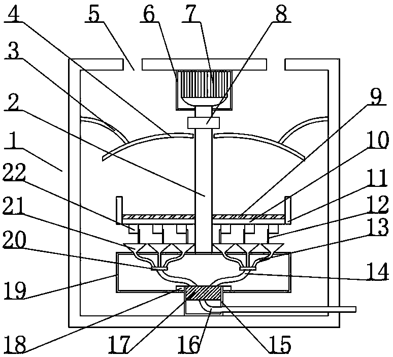
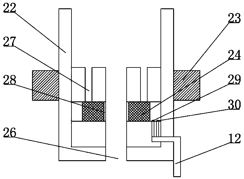
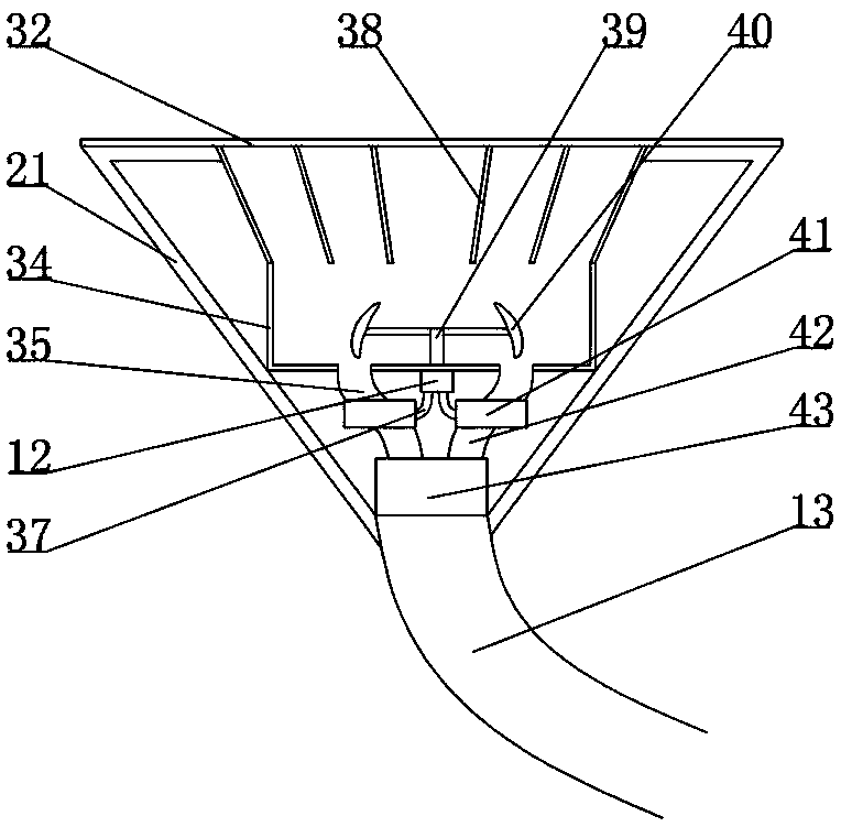
[0019] see Figure 1-4 , a drying device for auto parts, comprising a device body 1, a motor box 6 is arranged under the top plate of the device body 1, an air outlet 5 is arranged on the top plate outside the motor box 6, a motor 7 is arranged in the motor box, and an output shaft below the motor 7 is arranged A shaft coupling 8, a rotating shaft 2 is arranged below the coupling 8, a fixed frame 10 is arranged at the bottom of the rotating shaft 2, a breathable mesh 9 is arranged above the fixed frame 10, an annular baffle 11 is arranged outside the fixed frame 10, and a control box 22 is arranged below the fixed frame 10, The control box 22 is arranged on the fixed...


PUM


Abstract

The invention relates to the technical field of automobile parts, and discloses an automobile part drying device. The automobile part drying device comprises a device body, wherein an air outlet holeis formed in a top plate of the device body, a motor is arranged below the top plate of the device body, a rotating shaft is arranged below the motor, the lower part of the rotating shaft is providedwith a fixing frame, a ventilating mesh is arranged above the fixing frame, a control box is arranged below the fixing frame, a gas distributing pipe is arranged below the control box, a rotating boxis arranged below the gas distributing pipe, and a fixing box is arranged in the middle of the lower part of the rotating box. The moisture content in the part needing to be dried is detected throughthe control box, so that proper hot air is released by the gas distributing pipe, the part is dried, and the waste of hot gas is reduced; when the part in the control box is detected to be free of water, the gas distributing valve is automatically closed, the part can be dried without manual operation, the automation degree is high, meanwhile, the part can rotate in the device, and the drying effect is good.

Description

technical field [0001] The invention relates to the technical field of auto parts, in particular to an auto parts drying device. Background technique [0002] In modern society, automobiles provide great convenience for people's travel, and the automobile industry has also developed greatly. Among them, auto parts are the foundation of the automobile industry and a necessary factor for the sustainable and healthy development of the automobile industry. Independent innovation of parts It also has a strong driving force for the development of the vehicle industry. If the processing of parts is not emphasized, the quality of the vehicle cannot be further improved. The existing drying devices used in the processing of auto parts often fail to achieve a good quality. The drying effect can easily lead to uneven drying on the surface of parts and affect the production quality of parts. Sometimes in order to ensure the drying quality, parts are over-dried, resulting in waste of reso...

Claims


Application Information

Patent Timeline
Patent Type & Authority Applications(China)
IPC IPC(8): F26B11/18F26B21/00F26B25/00F26B25/02F26B25/18
CPCF26B11/18F26B21/001F26B25/00F26B25/02F26B25/18
Inventor 王盈盈
Owner 萍乡粤科技术服务中心
Learn More