Heating furnace and method for achieving uniform heating of heating furnace

A heating furnace and heater technology, applied in the field of heating furnace, can solve problems such as difficult to ensure forming size, product scrapping during forming process, over-burning, etc., achieve uniform heating and improve heating quality

Inactive Publication Date: 2019-11-01
CHINA ACADEMY OF MACHINERY SCIENCE & TECHNOLOGY +1
View PDF5 Cites 0 Cited by
  • Summary
  • Abstract
  • Description
  • Claims
  • Application Information

AI Technical Summary

Problems solved by technology

If the temperature is too low, it will increase the deformation resistance of the forming process, making it difficult to ensure the forming size. If the temperature is too high, it will easily cause overburning, which will directly cause the product to be scrapped during the forming process. Therefore, the temperature uniformity of the aluminum alloy plate must be controlled within ± Within 3℃~5℃

Method used


Image

  • Heating furnace and method for achieving uniform heating of heating furnace
  • Heating furnace and method for achieving uniform heating of heating furnace
  • Heating furnace and method for achieving uniform heating of heating furnace

Examples


Embodiment 1

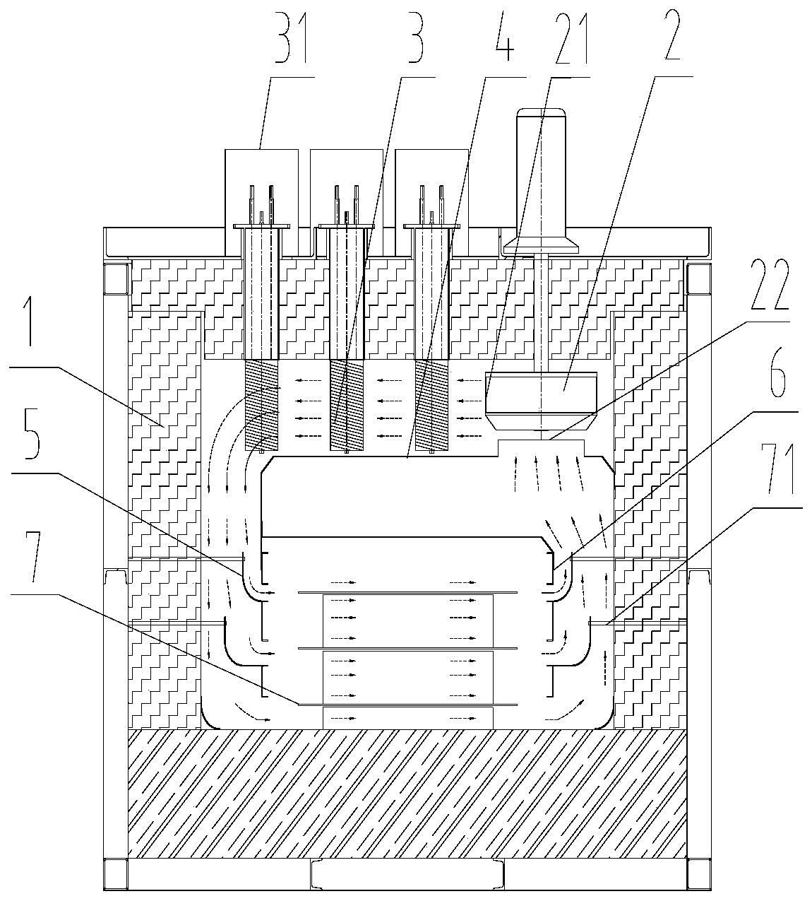
[0034] Such as Figures 1 to 3 As shown, a heating furnace includes a square airtight furnace body 1, a centrifugal fan 2 with air inlet and air outlet vertically arranged in the furnace body 1 on one side of the furnace body top, wherein the air inlet is vertically downward, and the air outlet is vertical. The tuyere is set horizontally, and the centrifugal fan 2 draws the air in the furnace body 1 into the air inlet, and then discharges it out of the furnace body 1 from the air outlet, so that the air in the furnace body 1 can continue to circulate; the top of the furnace body 1 is designed as a detachable bolt connection structure , to facilitate the maintenance of the parts in the furnace body 1.

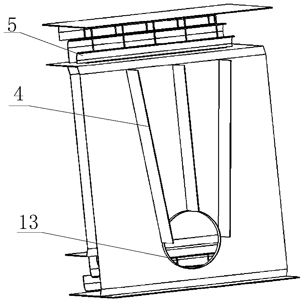
[0035] On the side of the air outlet of the centrifugal fan 2, a plurality of squirrel-cage heaters 3 fixed on the top of the furnace body and suspended in the furnace body 1 are arranged, and the air discharged from the air outlet is heated by the squirrel-cage heater 3 to beco...

Embodiment 2

[0045] The difference between this embodiment and Embodiment 1 is that the furnace is arranged at the top of the furnace body, the centrifugal fan is arranged at the bottom of the furnace body 1, and the heater is arranged on the exhaust route of the centrifugal fan, so that the outlet of the centrifugal fan After being heated by the heater, the air discharged from the tuyeres is guided by the horizontal air duct and enters the furnace through each furnace air inlet to heat the aluminum plate on the heating platform 7 .

[0046] The method of heating furnace to achieve uniform heating

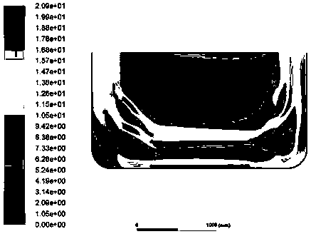
[0047] In addition to the setting of the first baffles of the heating furnace protruding from the top to the bottom layer by layer, it is also necessary to use optimization analysis software as an optimization tool to measure the distance of the upper end of the first baffles on each layer 1. The height of the first deflector on each layer from the inside of the bottom of the furnace, the shape...


PUM


Abstract

The invention discloses a heating furnace and a method for achieving uniform heating of the heating furnace. An air inlet and an air outlet of a centrifugal fan (2) of the heating furnace are formed in the furnace body (1); a plurality of heaters are arranged on an exhaust route of the air outlet of the centrifugal fan (2) in the furnace body (1); a plurality of first guide plates (5) are arrangedand the outer sides of each hearth air inlet and outlet are each provided with one first guide plate (5) which is longer than the lengths of the hearth air inlet and outlet; the lower ends of the first guide plates (5) are close to the lower ends of the hearth air inlet and outlet; and the upper ends of the first guide plates (5) are gradually away from the hearth air inlet and outlet from top tobottom. According to the heating furnace, each optimal design variable value corresponding to the condition that the wind speed passing through the air inlet and the air outlet in the hearth is basically consistent is found through the optimal method, and each optimal design variable value is set according to the optimal design variable value, so that a workpiece to be heated is heated uniformlyby the heating furnace, and the heating quality is good.

Description

technical field [0001] The invention belongs to the technical field of heat treatment of sheet metal parts, in particular to a heating furnace and a method for realizing heating uniformity of the heating furnace. Background technique [0002] In order to cope with the energy crisis and protect the environment, the lightweight of passenger cars has become a major trend in the development of the automotive industry. Compared with steel, aluminum alloy has the advantages of light weight, high specific strength, and corrosion resistance. The use of aluminum alloy materials for auto parts is the most effective way to reduce the weight of automobiles. [0003] The aluminum alloy HFQ process, that is, the in-mold quenching of aluminum alloy hot solution forming, is an integrated process of aluminum alloy solution treatment and hot forming, and the purpose is to obtain aluminum alloy parts with complex shapes and high strength. Before deformation, the aluminum plate is heated and k...

Claims


Application Information

Patent Timeline
IPC IPC(8): F27D7/04F27D1/18
CPCF27D1/1858F27D7/04F27D2007/045
Inventor 张文良李贤君宋金升罗平吴佳龙孙立壮周彤
Owner CHINA ACADEMY OF MACHINERY SCIENCE & TECHNOLOGY
Why Eureka
Try Eureka