Drying chamber

A technology of drying room and air supply room, which is applied in the field of drying room, can solve problems such as inability to adjust, and achieve simple, low-cost and low-cost effects

Inactive Publication Date: 2019-11-01
M加W集团有限公司
View PDF11 Cites 1 Cited by
  • Summary
  • Abstract
  • Description
  • Claims
  • Application Information

AI Technical Summary

Problems solved by technology

No adjustments are possible in this known design of the drying chamber

Method used


Image

  • Drying chamber
  • Drying chamber
  • Drying chamber

Examples


Embodiment Construction

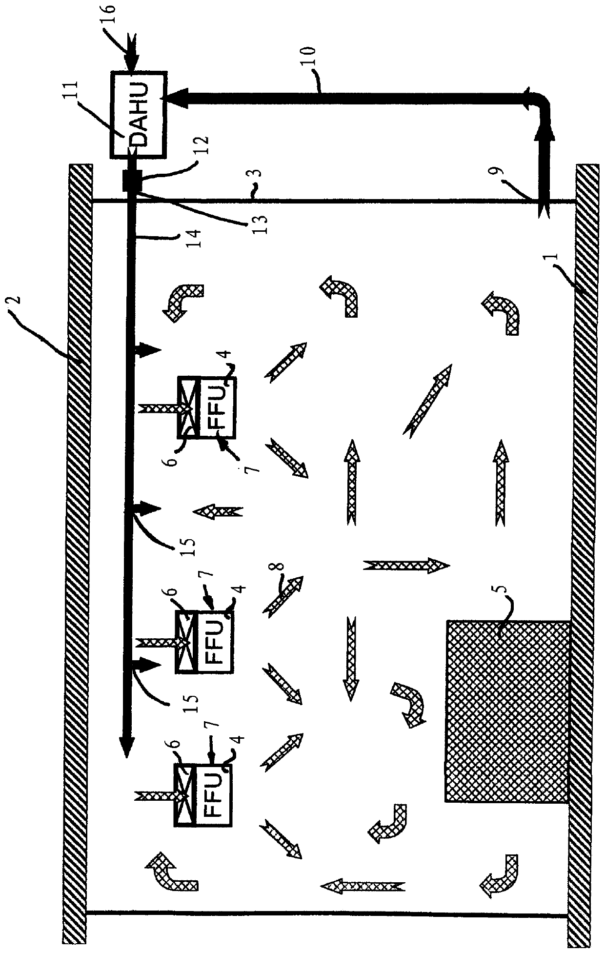
[0028] The drying chamber described below is used in particular for the production of lithium-ion batteries. However, they can also be used advantageously, for example in the pharmaceutical industry or the food industry.

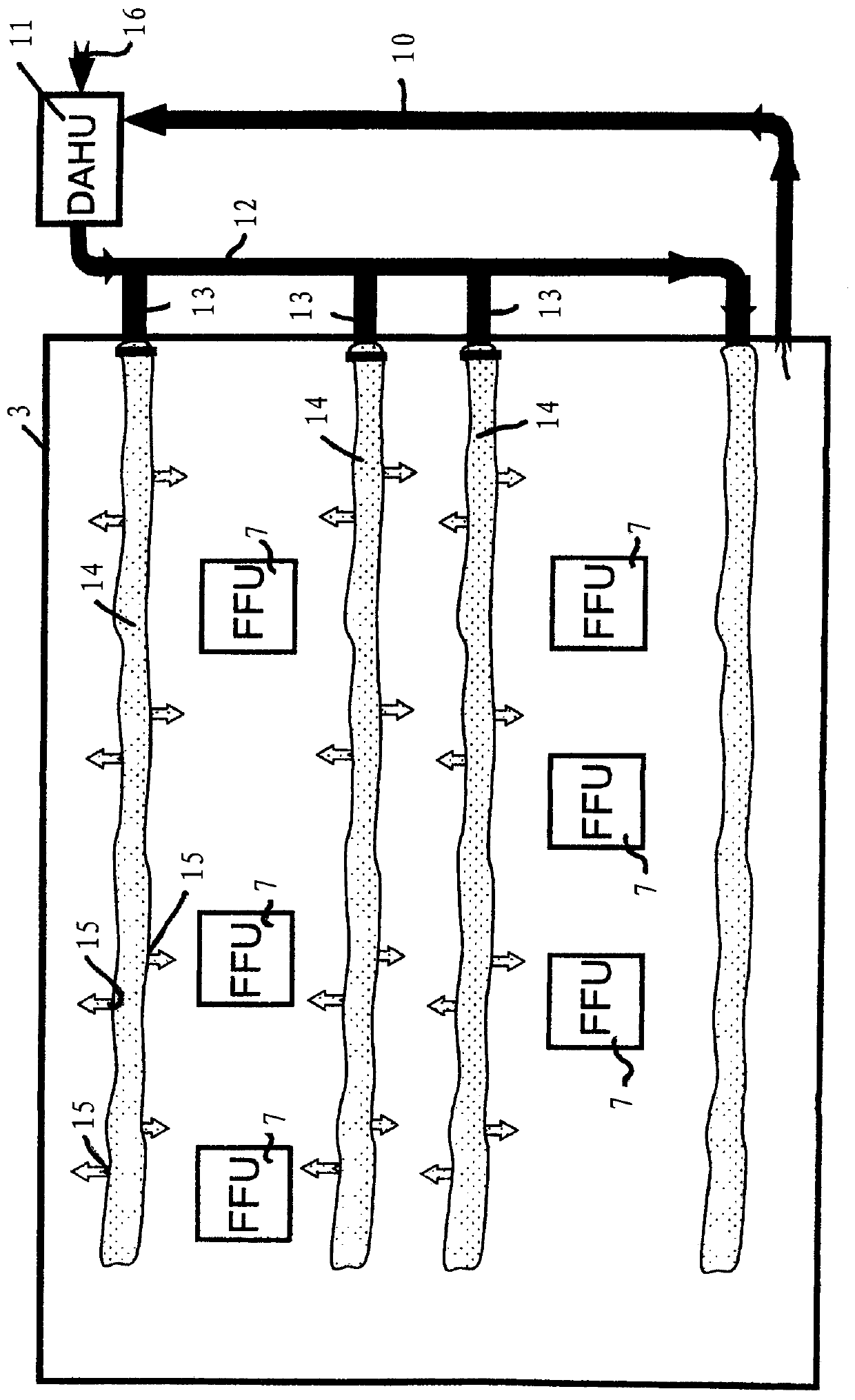
[0029] according to figure 1 with 2 The drying room has a floor 1 and a ceiling 2 supported on the floor 1 by vapor diffusion sealed side walls 3 . as by figure 2 It can be seen that the drying chamber has, for example, a rectangular outline. But the drying chamber is not limited to this cross-sectional shape. It can have, for example, a square outline, a hexagonal outline or, for example, a circular outline.

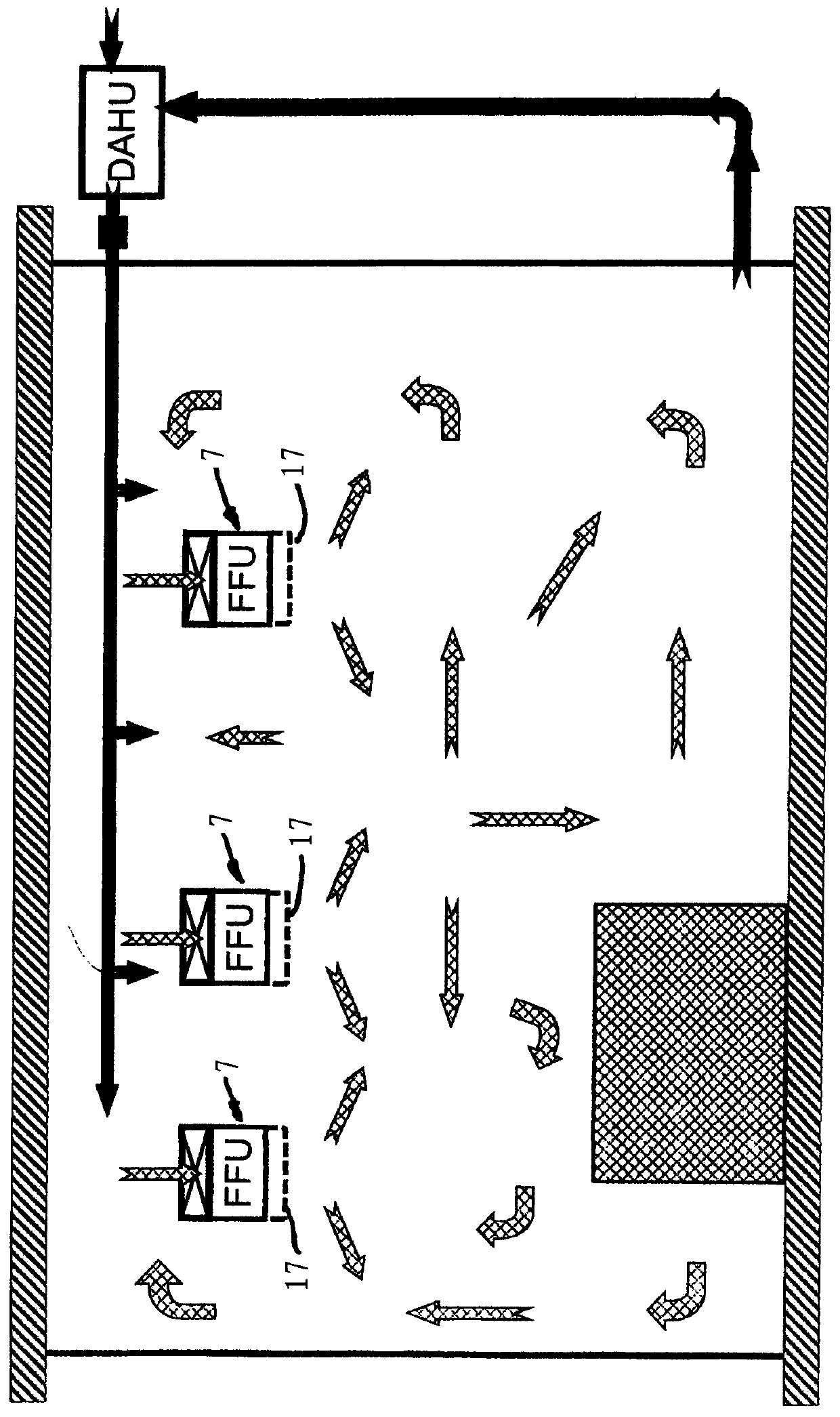
[0030] Air delivery / cooling units 7 are distributed in the drying chamber. They each include an air delivery unit 4 , which in the exemplary embodiment is formed as a filter-fan unit, and a cooling unit 6 . Here, these air delivery / cooling units 7 are only arranged in the drying chamber where filtered air is required. exist figure 1 is shown...


PUM


Abstract

The invention relates to a drying chamber comprising an air-conveying device which has at least one fan. The drying chamber also comprises a cooling device for the conveyed air. The air-conveying device is formed by individual air-conveying units (4), and the cooling device is formed by individual coolers (6). The air-conveying units (4) and the coolers (6) are combined to form autonomous air-conveyors / cooling units (7) respectively.

Description

technical field [0001] The invention relates to a drying chamber according to the preamble of claim 1 . Background technique [0002] Often, the product must be handled and / or processed in a drying room. Filter elements are arranged at grid intervals on the grid ceiling of the clean room, to which filter elements are supplied with dry air via supply channels. At least one cooler, one heat exchanger and one blower are arranged in sequence in the supply channel along the flow direction. The air located in the drying chamber is sucked into the supply channel by means of the blower. All air is directed through the cooler and cooled to the desired level. The cooled air reaches the filters, through which the air flows back into the drying chamber again. Energy consumption is relatively high since most of the dry air has to be directed through coolers and blowers in the supply channel. Dry air is evenly distributed in the drying chamber by filter elements. However, it is ofte...

Claims


Application Information

Patent Timeline
IPC IPC(8): F26B21/00F24F3/00F24F1/0073F24F1/0083
CPCF26B3/04F26B9/06F26B21/02F24F1/0047F24F3/167F24F1/0073F24F1/0083
Inventor J·霍夫曼H.鲍尔R·西蒙
Owner M加W集团有限公司
Why Eureka
Try Eureka