Integrated transformer and integrated switching power supply application circuit using the integrated transformer

An integrated transformer and integrated switch technology is applied in the direction of transformer/inductor magnetic core, transformer/inductor parts, transformers, etc. It can solve the problems of large volume, high design cost, and large space of the charger, and achieve small volume Effect

Active Publication Date: 2021-10-19
SHINRY TECH
View PDF7 Cites 0 Cited by
  • Summary
  • Abstract
  • Description
  • Claims
  • Application Information

AI Technical Summary

Problems solved by technology

[0003] The purpose of the present invention is to provide an integrated transformer and an integrated switching power supply application circuit using the integrated transformer, which not only solves the problem of the large volume of the charger caused by using two transformers in parallel to increase the output power in the traditional solution It also solves the technical problem that the charger and DC-DC occupy a large space and the design cost is high due to the separate arrangement or physical integration of two sets of independent conversion circuits for the charger and DC-DC.

Method used


Image

  • Integrated transformer and integrated switching power supply application circuit using the integrated transformer
  • Integrated transformer and integrated switching power supply application circuit using the integrated transformer
  • Integrated transformer and integrated switching power supply application circuit using the integrated transformer

Examples


Embodiment Construction

[0024] The following will clearly and completely describe the technical solutions in the embodiments of the present invention with reference to the accompanying drawings in the embodiments of the present invention. Obviously, the described embodiments are only some, not all, embodiments of the present invention. Based on the embodiments of the present invention, all other embodiments obtained by persons of ordinary skill in the art without creative efforts fall within the protection scope of the present invention.

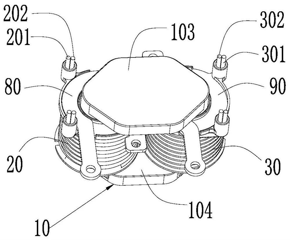
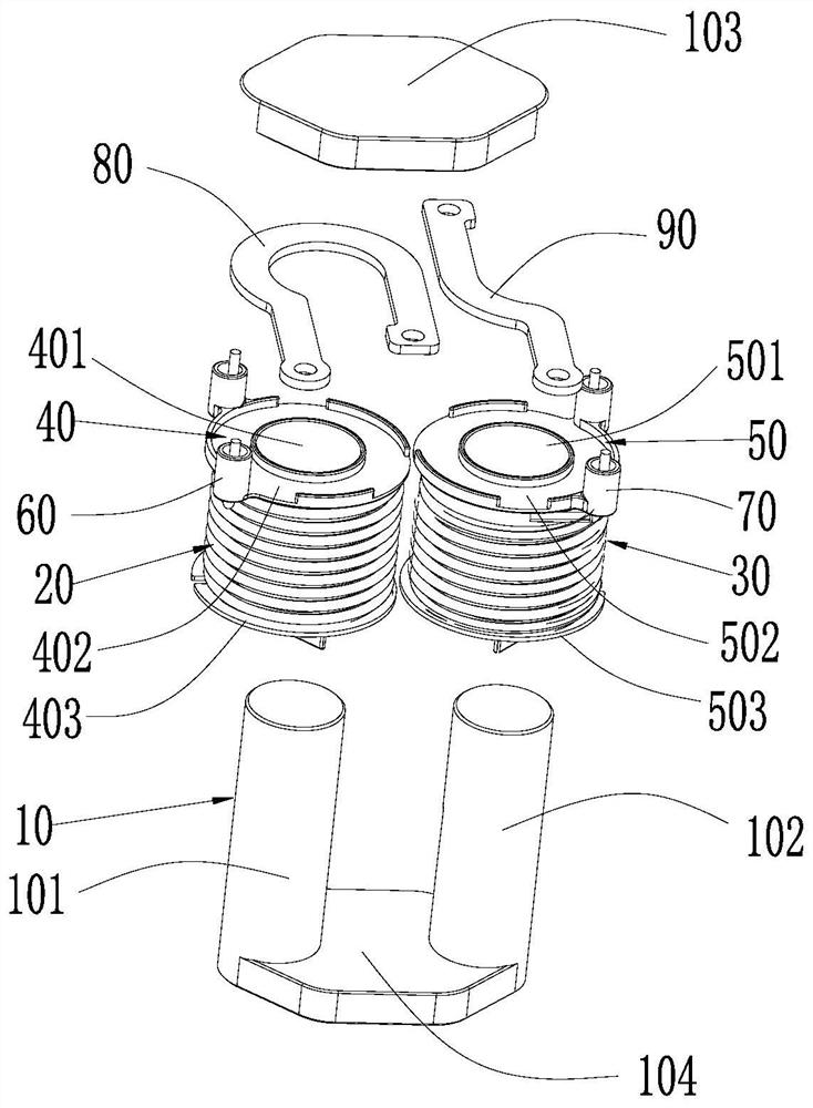
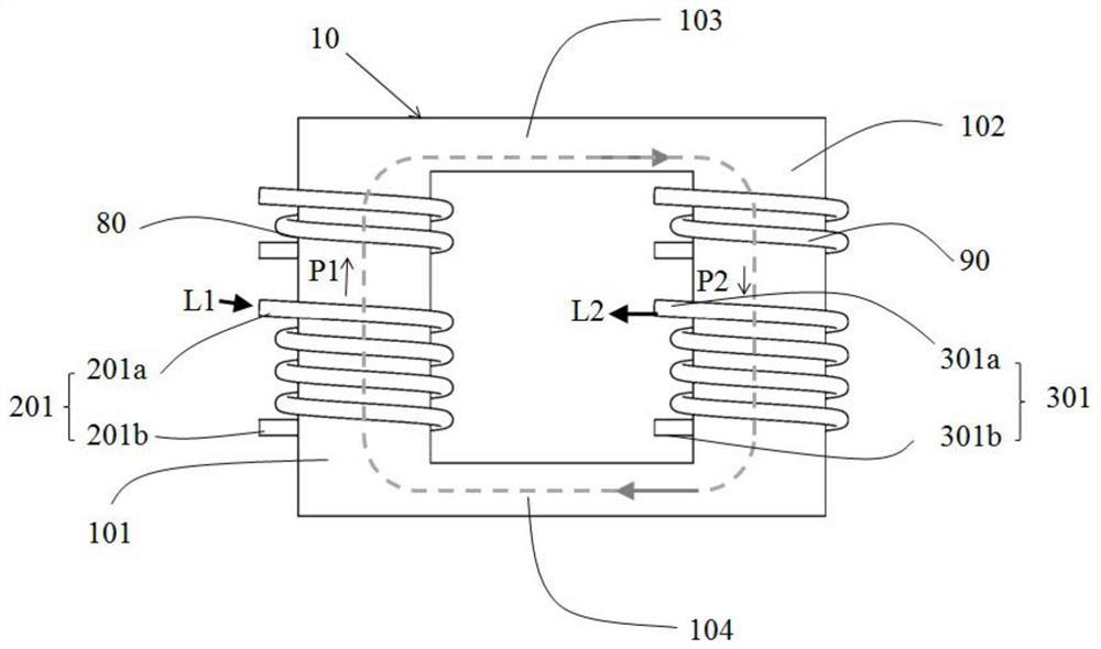
[0025] see Figure 1-2 , the present invention provides an integrated transformer 100 , including a closed magnetic core 10 , a first winding 20 , a second winding 30 , a third winding 80 , a fourth winding 90 , a first bobbin 40 and a second bobbin 50 . The closed magnetic core 10 includes a first magnetic column 101 and a second magnetic column 102 which are parallel and opposite to each other. The first frame 40 is sleeved on the first magnetic column 101 , and ...


PUM


Abstract

An integrated transformer (100) and an integrated switching power supply application circuit including the integrated transformer, the integrated transformer includes a closed magnetic core (10), a first winding (20), a second winding (30), and a third winding (80) , a fourth winding (90), a first skeleton (40) and a second skeleton (50), the closed magnetic core includes a first magnetic column (101) and a second magnetic column (102) which are parallel and oppositely arranged, the first skeleton Set on the first magnetic column, the first winding is wound on the first bobbin, the second bobbin is sleeved on the second magnetic post, the second winding is wound on the second bobbin, and the third winding is wound on the first magnetic post , and spaced from the first winding, the fourth winding is wound on the second magnetic column, and spaced from the second winding, the first winding includes the first primary winding (201) and the first secondary winding (202) , the second winding includes a second primary winding (301) and a second secondary winding (302), the first primary winding is used to feed the first current (L1), and the second primary winding is used to feed the second The current (L2), the first current and the second current are used to form a magnetic flux loop in the closed magnetic core. The integrated transformer solves the technical problem that two transformers used in parallel occupy a large space.

Description

technical field [0001] The invention relates to the field of transformers, in particular to an integrated transformer and an integrated switching power supply application circuit of a new energy vehicle using the integrated transformer. Background technique [0002] With the rapid development of new energy vehicles and the increase of cruising range, the requirements for the charging power, voltage and current of the charger are getting higher and higher. In the traditional solution, two transformers are connected in parallel to increase the output power. Realization, when two transformers are used in the charger to output in parallel, the volume of the charger is larger and the process is more complicated. At the same time, the traditional charger and DC-DC (direct-current converter) are also arranged separately using two sets of independent conversion circuits or applied to the whole vehicle through physical integration. This independent arrangement also leads to the charg...

Claims


Application Information

Patent Timeline
Patent Type & Authority Patents(China)
IPC IPC(8): H01F30/06H01F30/04H01F27/24H01F27/28H01F27/30H02J7/00H02M3/22
CPCH01F27/24H01F27/28H01F27/306H01F30/04H01F30/06H02J7/0013H02M3/22H01F27/30H02J7/00
Inventor 赵德琦程静吴壬华
Owner SHINRY TECH
Why Eureka
Try Eureka