Chamfering machine

A technology of chamfering machine and chamfering mechanism, which is applied in the field of chamfering machine, can solve the problems of inconvenient processing operation and cleaning, complex structure of chamfering machine, dirty machine, etc., and achieve low cost, high production efficiency and convenient operation Effect

Pending Publication Date: 2019-11-05
浙江飞宇自动化科技股份有限公司
View PDF0 Cites 1 Cited by
  • Summary
  • Abstract
  • Description
  • Claims
  • Application Information

AI Technical Summary

Problems solved by technology

For the cylindrical workpiece, the chamfering part is at the end. The current chamfering machine usually uses a very complicated fixture to clamp the workpiece, and an oil cylinder is used to drive the fixture, which makes the structure of this type of chamfering machine complex and bulky. Huge, high cost, and the oil cylinder will make the machine full of oil, stick the debris generated by the chamfering process, it is not easy to process and clean, and the whole machine is dirty

Method used


Image

  • Chamfering machine
  • Chamfering machine
  • Chamfering machine

Examples


Embodiment Construction

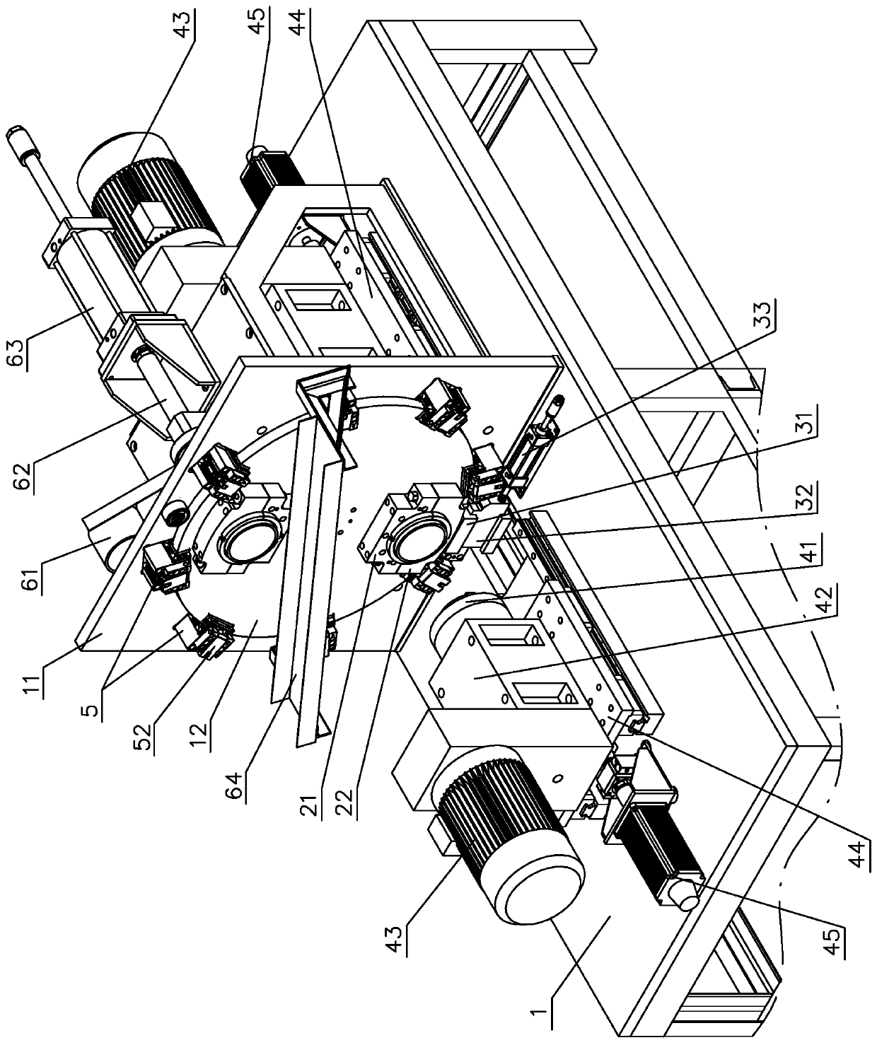
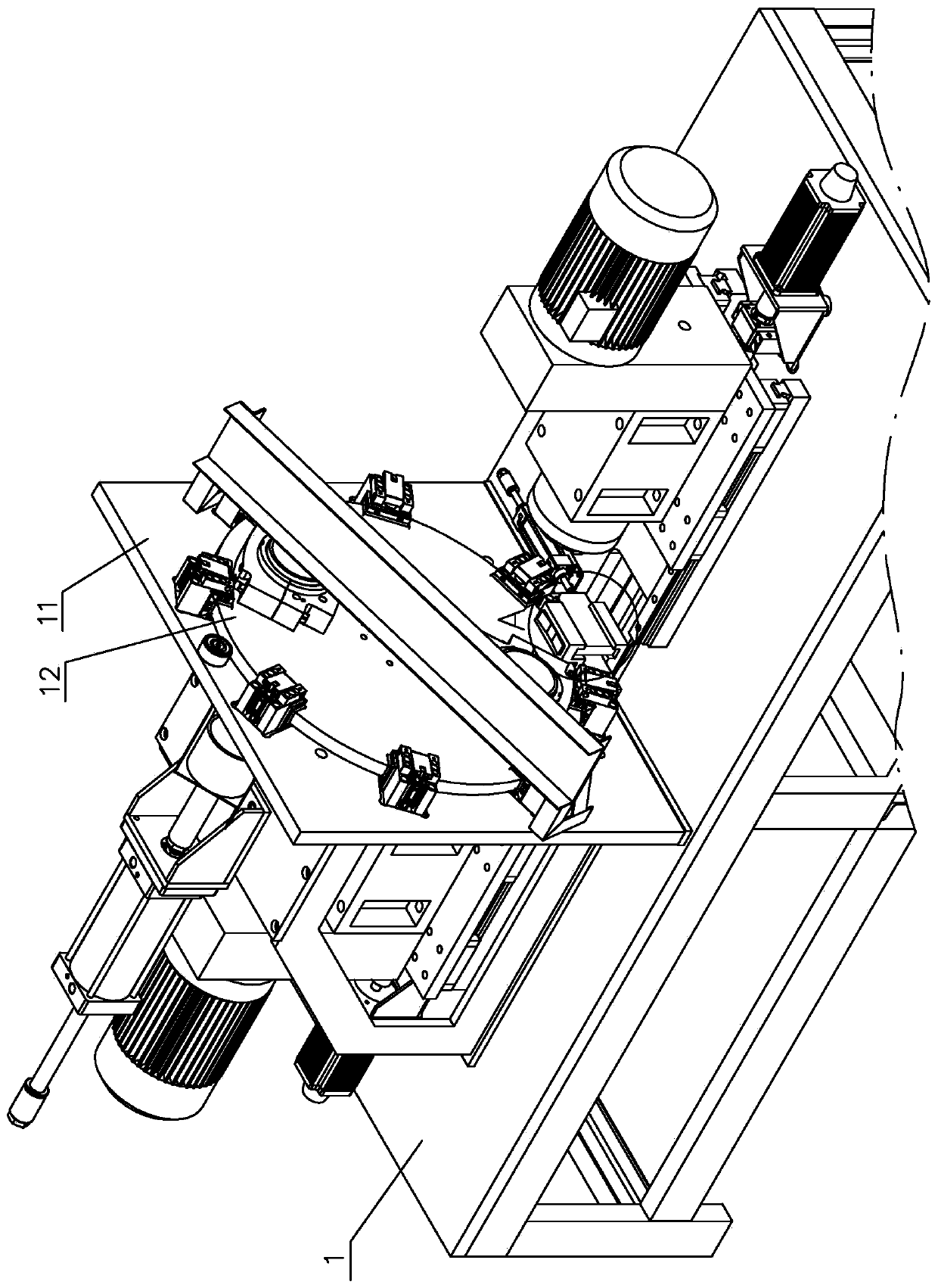
[0017] see figure 1 and figure 2 , The chamfering machine includes a machine table 1, a fixture, a propulsion mechanism and a chamfering mechanism. The machine table 1 includes a vertical vertical plate 11 and a turntable 12 arranged parallel to the vertical plate 11. The turntable 12 can rotate on the vertical plate 11, and the rotation axis is in the horizontal direction.

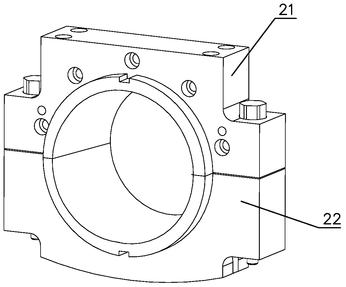
[0018] The fixture is arranged on the turntable 12, and is used for clamping the cylindrical workpiece (such as a bearing sleeve, etc.). see image 3 and Figure 4 , the fixture includes an upper fixture 21, a lower fixture 22 and a return spring 23. The upper fixture 21 is fixed on the turntable 12 with screws, and the lower fixture 22 is movably arranged on the upper fixture 21. Under the action of an external force, it can move up and down relative to the upper fixture 21. move. The upper clamp 21 has an arc-shaped upper clamping surface 210 on a surface opposite to the lower clamp 22 , and the l...


PUM


Abstract

The invention relates to a chamfering machine. The chamfering machine comprising a machine table, a clamp, a chamfering mechanism and a propelling mechanism, the propelling mechanism comprises an upper sliding block and a lower sliding block, wherein the upper sliding block and the lower sliding block are arranged on the machine table, the upper sliding block can move up and down relative to the machine table, the upper sliding block is located above the lower sliding block and is pressed on the lower sliding block, and the lower sliding block can move back and forth relative to the machine table; the clamp comprises an upper clamp, a lower clamp and a reset spring, the upper clamp is arranged on the machine table, the lower clamp is movably arranged on the upper clamp, the upper sliding block is located below of the lower clamp, the upper sliding block moves forwards or backwards to push the upper sliding block to move upwards, and the upper sliding block moves upwards to push the lower clamp to move towards the upper clamp; the upper clamp and the lower clamp together clamp a workpiece, when the lower sliding block retracts, the upper sliding block moves downwards, and the resetspring enables the upper clamp and the lower clamp to return to a non-clamping state. According to the chamfering machine, the workpiece is clamped by adopting a simple mechanical structure, the non-clamping state is automatically restored after the clamp thrust is released, the structure of the whole machine is very simple, the operation is convenient, the cost is low and the production efficiency is high.

Description

technical field [0001] The invention relates to the technical field of machining equipment, in particular to a chamfering machine. Background technique [0002] Chamfering refers to the processing of cutting the edges and corners of the workpiece into a certain slope. The chamfering is to remove the burrs on the parts due to machining, and also to facilitate the assembly of the parts. Generally, the chamfering is made at the end of the parts. The chamfering machine generally clamps the workpiece with a fixture first, and then uses the chamfering mechanism to chamfer the workpiece. For different workpieces, due to the different shapes and chamfering parts of the workpieces, the fixtures used are also different. For the cylindrical workpiece, the chamfering part is at the end. The current chamfering machine usually uses a very complicated fixture to clamp the workpiece, and an oil cylinder is used to drive the fixture, which makes the structure of this type of chamfering mach...

Claims


Application Information

Patent Timeline
IPC IPC(8): B23C3/12B23Q7/14
CPCB23C3/126B23Q7/14
Inventor 李四根
Owner 浙江飞宇自动化科技股份有限公司
Why Eureka
Try Eureka