Intelligent dyeing equipment for rainbow lines

A rainbow and equipment technology, which is applied to the processing of textile materials, equipment configuration, textiles and papermaking, and removal of liquid/gas/steam, etc. It can solve the problems of affecting the dyeing effect, the transition part is not natural, and the dyeing efficiency is low. Improve dyeing efficiency, natural color transition, and prevent decolorization

Inactive Publication Date: 2019-11-05
廖彬
View PDF5 Cites 2 Cited by
  • Summary
  • Abstract
  • Description
  • Claims
  • Application Information

AI Technical Summary

Problems solved by technology

Dyeing the rainbow thread in this way requires the staff to continuously tighten and dip the thread material, resulting in low dyeing efficiency; moreover, dyeing the thread material in sections will make the transition between each color less obvious. Natural, thus affecting the dyeing effect

Method used


Image

  • Intelligent dyeing equipment for rainbow lines
  • Intelligent dyeing equipment for rainbow lines
  • Intelligent dyeing equipment for rainbow lines

Examples


Embodiment 1

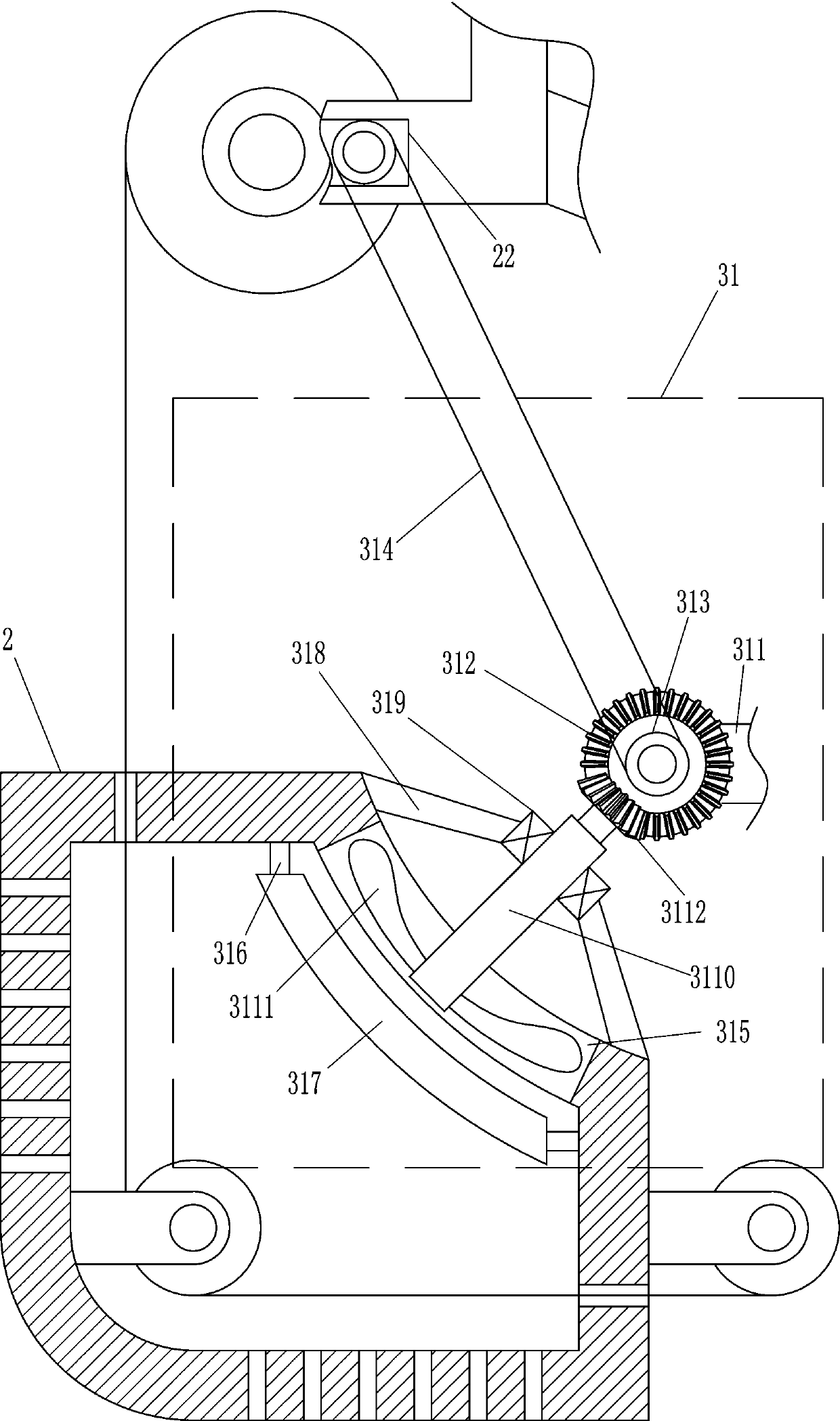
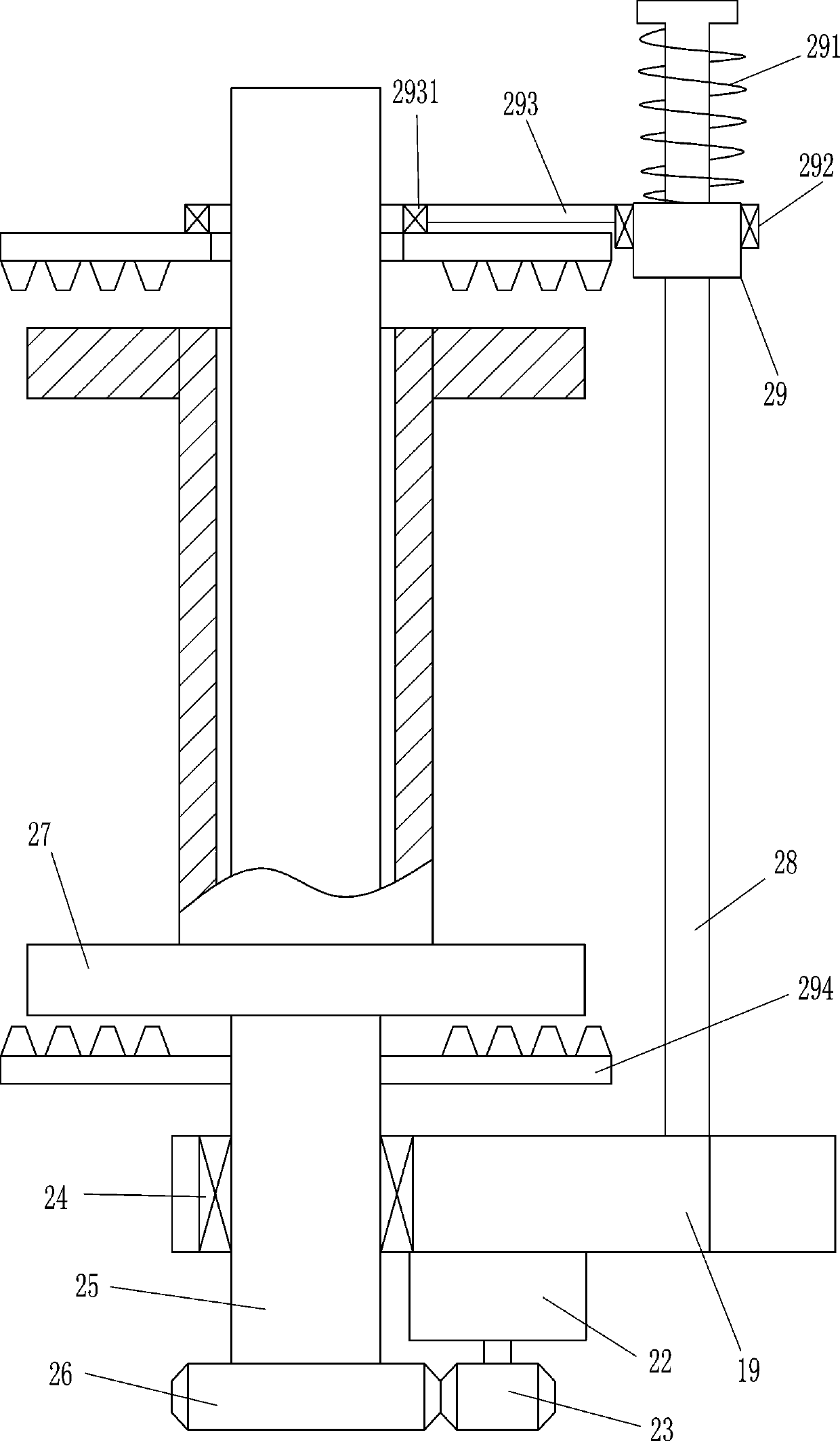
[0024] A rainbow thread intelligent dyeing equipment, such as figure 1 , figure 2 , Figure 7 and Figure 8As shown, it includes a bottom plate 1, a drying box 2, a first pulley 5, a second pulley 6, a first pole 7, a second pole 8, a connecting plate 10, a feeding pipe 11, a water pump 12, and a filling pipe 13. Liquid storage joint 14, spray head 15, third pulley 16, inclined rod 18, L-shaped plate 19, wire sleeve 20, fourth pulley 21, drive motor 22, first gear 23, first bearing seat 24, second One rotating rod 25, the second gear 26, the bobbin 27, the guide rail 28, the guide sleeve 29, the spring 291, the second bearing seat 292, the fixed rod 293, the third bearing seat 2931, the splint 294, the control box 101, the power supply assembly Switch 102, intelligent blanking device 30 and drying device 31, a drying box 2 is provided on the left side of the top of the bottom plate 1, and a first through hole 3 is opened on the left part of the upper wall of the drying box...

Embodiment 2

[0031] On the basis of Example 1, such as Figure 5 As shown, it also includes a closed box 321, a sealing ring 322, a waste liquid pipe 324, a placement plate 325 and a collection box 326, a closed box 321 is arranged between the first pole 7 and the top of the second pole 8, and the liquid storage joint 14 and the spray head 15 are located in the closed box 321, the middle part of the left and right walls of the closed box 321 has a fourth through hole 323, the fourth through hole 323 communicates with the third through hole 17, embedded in the middle of the closed box 321 upper wall A sealing ring 322 is provided, the filling pipe 13 passes through the sealing ring 322, a waste liquid pipe 324 is connected in the middle of the lower wall of the closed box 321, and a placement plate 325 is arranged between the first pole 7 and the upper part of the second pole 8, and the The plate 325 is located under the closed box 321 , and the collecting box 326 is placed on the placing p...


PUM


Abstract

The invention relates to dyeing equipment, in particular to intelligent dyeing equipment for rainbow lines. The technical purpose of providing the intelligent dyeing equipment which is high in dyeingefficiency and natural in transition part between dyes of different colors for the rainbow lines is achieved. According to the technical scheme, the intelligent dyeing equipment for the rainbow linescomprises a bottom plate, a drying box, a first pulley, a second pulley and the like; the drying box is arranged on the left side of the top of the bottom plate, and first through holes are formed inthe left portion of the upper wall of the drying box and the lower portion of the right wall of the drying box respectively. Accordingly, an intelligent feeding device and the drying device operate simultaneously, dyeing and drying can be conducted simultaneously, in this way, the dyeing efficiency is greatly improved, the dyed rainbow lines are dried in time, the rainbow lines can be subjected tofixation in time, and decoloration is prevented. The dye sprayed from a spray head can flow into a enclosed container for re-mixing to form a gradient ramp, in this way, the dyed rainbow lines can bemore natural in color transition, and then the dyed rainbow lines are more attractive.

Description

technical field [0001] The invention relates to a dyeing device, in particular to a rainbow thread intelligent dyeing device. Background technique [0002] Rainbow thread is dyed by 7 dyes of red, orange, yellow, green, blue, blue and purple. As an important textile material, it is widely used in the field of textile production. Nowadays, the dyeing of rainbow thread is generally done by using the tie-dye technique. First, a large amount of white thread is tied up and then immersed in the lightest dye solution of the required color. Tighten it, dye it with the second color, and then tie it tightly and dip it, let another color be dyed again, and repeat the operation until the color reaches the ideal state. Dyeing the rainbow thread in this way requires the staff to tie up and dip the thread material continuously, resulting in low dyeing efficiency; and dyeing the thread material in sections will make the transition between each color less obvious. Naturally, thus affecting...

Claims


Application Information

Patent Timeline
IPC IPC(8): D06B1/02D06B23/20D06B15/00
CPCD06B1/02D06B15/00D06B23/20
Inventor 廖彬
Owner 廖彬
Why Eureka
Try Eureka