Dryer and drying apparatus with enhanced moisture removal

a drying apparatus and moisture removal technology, applied in the field of drying machines, can solve the problems of less than desirable drying articles, a certain amount of time to dry, and the like, and achieve the effects of improving the condition of air moisture, reducing the amount of time needed, and improving drying efficiency

Inactive Publication Date: 2010-08-31
PROTEGE ENTERPRISES
View PDF16 Cites 8 Cited by
  • Summary
  • Abstract
  • Description
  • Claims
  • Application Information

AI Technical Summary

Benefits of technology

[0006]The disclosed embodiments of the present invention relate to a dryer apparatus that improves drying efficiency and reduces the amount of time needed to dry articles within the apparatus. The dryer removes moisture from the air prior to entering the tumbler or housing with the dryer that holds the articles. The disclosed embodiments of the present invention seek to improve the condition of the air moisture prior to drying.
[0007]If the grains per pound of water vapor of the air to be heated are low, then the articles within the dryer are dried faster. The relationship is established because the vapor pressure is reduced by less grains / lb., which results in a quicker drying period. Thus, the time to dry an article is reduced. Preferably, a grain count of about 10 to 40 grains / lb. reduces the drying period to about a third of the normal drying period.
[0008]Vapor pressure dictates how much energy is needed to evaporate the water from the drying article. A certain amount of energy, such as about 1060 British Thermal Units (BTUs), is needed to evaporate 1 pound of air. Reducing the vapor pressure in that air would reduce the amount of energy needed to evaporate the pound of air. Vapor pressure may vary according to location and other conditions, but it can almost always be reduced. The disclosed embodiments of the present invention relates to reducing the vapor pressure in air so as to generate better air for drying clothes and lower costs. Thus, the disclosed embodiments of the present invention reduces the grains / lb of the air flowing into the dryer from the outside to improve drying times and efficiency.

Problems solved by technology

Articles, such as clothes, towels, rugs and the like, take a certain amount of time to dry.
Dryers use the vapor pressure of the air in the home, laundry room, basement and the like, which can be less than desirable for drying articles.

Method used


Image

  • Dryer and drying apparatus with enhanced moisture removal
  • Dryer and drying apparatus with enhanced moisture removal
  • Dryer and drying apparatus with enhanced moisture removal

Examples


Embodiment Construction

[0019]Aspects of the invention are disclosed in the accompanying description. Alternate embodiments of the present invention and their equivalents are devised without parting from the spirit or scope of the present invention. It should be noted that like elements disclosed below are indicated by like reference numbers in the drawings.

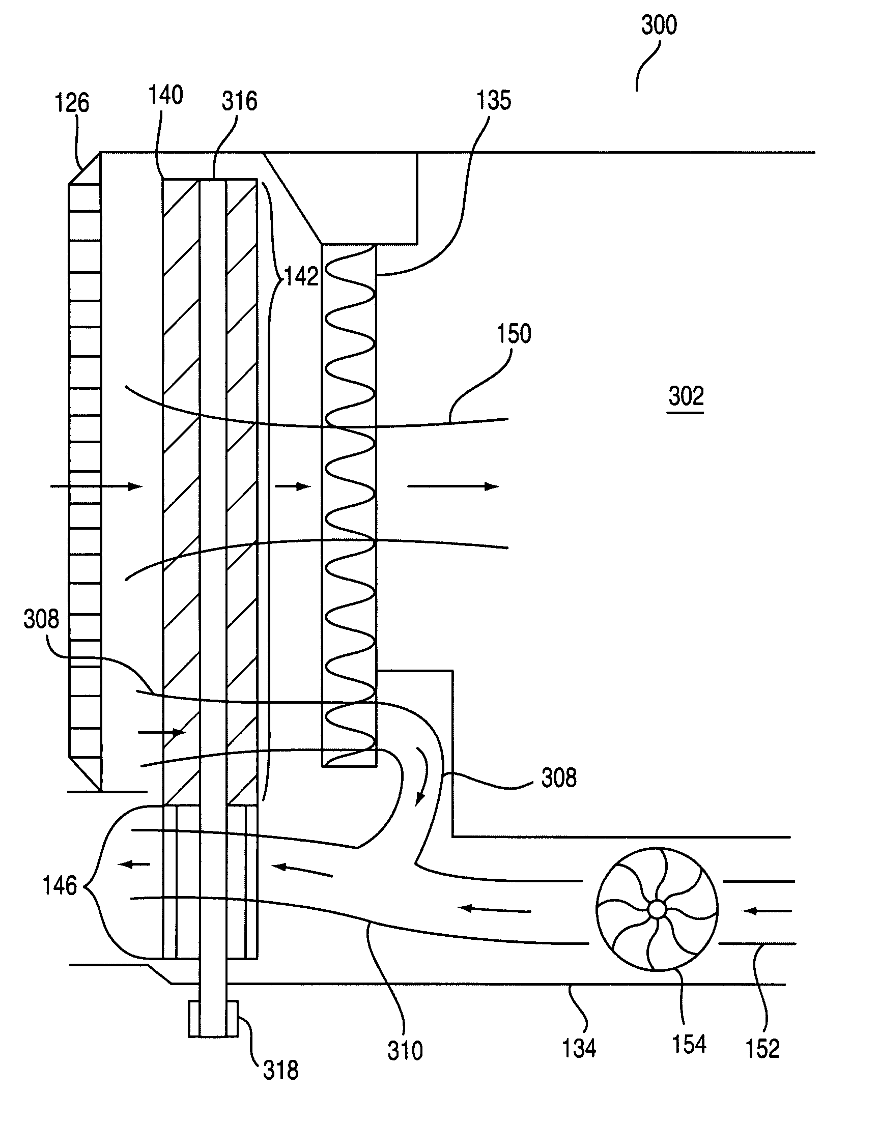
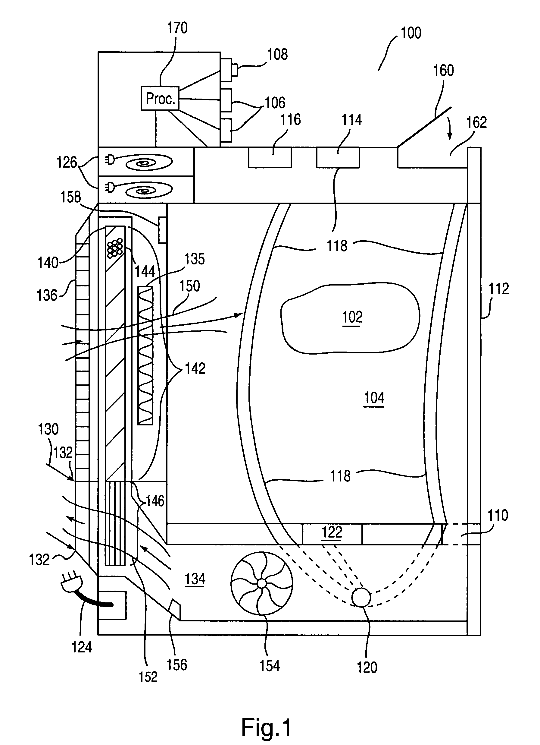
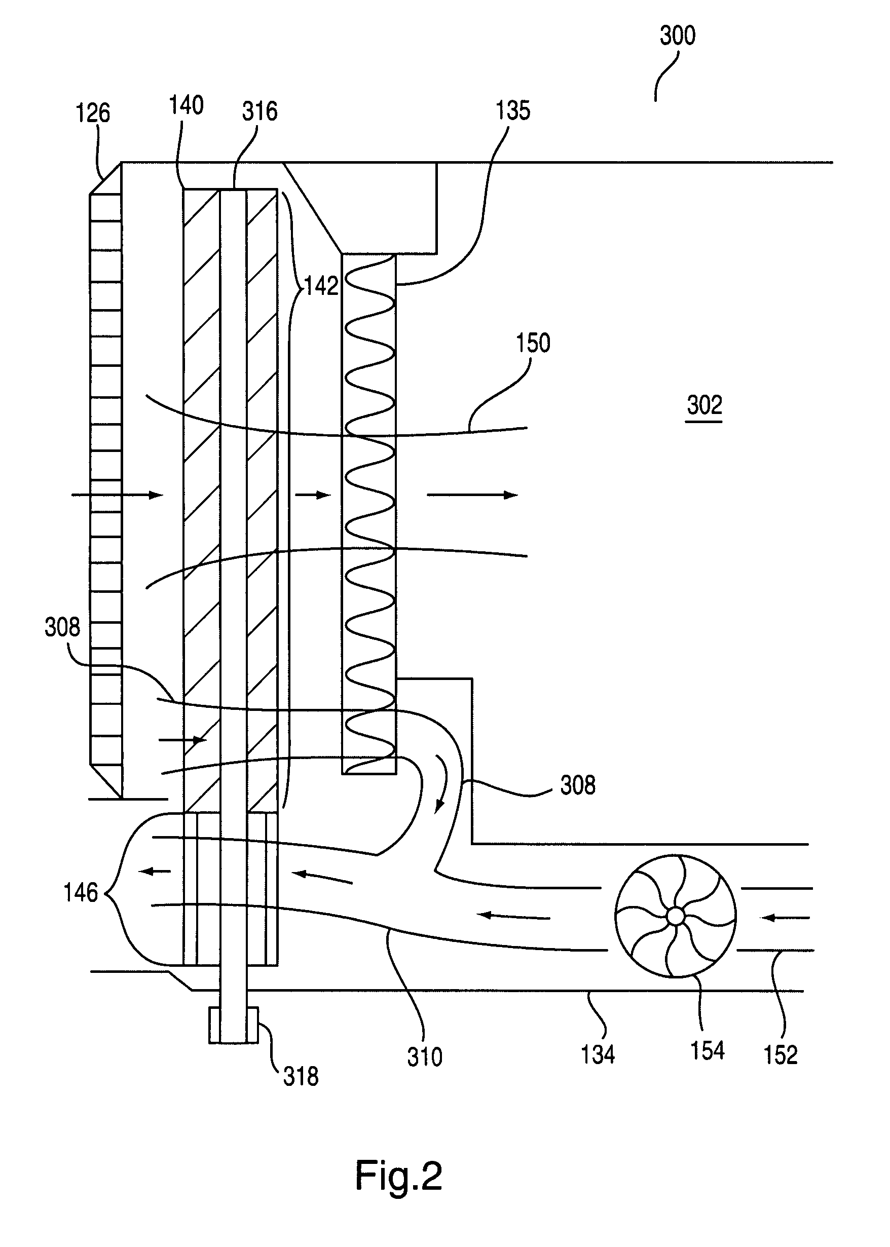
[0020]FIG. 1 depicts a dryer 100 having a desiccant wheel 140 according to the disclosed embodiments. Dryer 100 is a dryer using forced, heated air to remove moisture and wetness from articles, such as clothes, towels, fabric, dishes, household items, and the like. Article 102 represents one of such articles, or a plurality of articles, within dryer 102. Preferably, article 102 is contained within a rotating drum 104. Article 102 tumbles within drum 104 to allow the heated air to flow over its surface to remove moisture.

[0021]Dryer 100 intakes outside air from its surrounding environment and expels the air after it has cycled through drum 104. This proc...


PUM


Abstract

A dryer and a drying apparatus attachable to a dryer are disclosed. A wheel having desiccant material is located in line and in close proximity with a heating element. The wheel includes a first portion positioned in an inlet air path and a second portion positioned in an outlet air path. The desiccant material removes water molecules from air within the inlet air path, and lowers the vapor pressure of the incoming air. In the outlet air path, heated air flows through the second portion to transfer energy to the desiccant material. The wheel rotates to change the desiccant material within the portions.

Description

BACKGROUND OF THE INVENTION[0001]The present invention relates to a dryer using heated air to dry items. More particularly, the present invention relates to a dryer using a desiccant wheel to enhance moisture removal from the air.DISCUSSION OF THE RELATED ART[0002]Clothes dryers basically work in the same manner. The dryer sucks in air from the surrounding area. The dryer heats the air using an electric heating element, a gas burner and the like. The air passes into a tumbler housed within the dryer once it is heated. The hot air evaporates water from the clothes as they spin inside the tumbler. The dryer then forces the water evaporated from the clothes along with the hot air outside its assembly. Typically, a vent allows the air and moisture to exit the room.[0003]Articles, such as clothes, towels, rugs and the like, take a certain amount of time to dry. The amount of time varies according to the article being dried. Other factors to this time period are energy capacity of the hea...

Claims


Application Information

Patent Timeline
Patent Type & Authority Patents(United States)
IPC IPC(8): B01D53/06
CPCD06F58/20D06F58/24
Inventor DEWALD, III, CHARLES ROBERTCRISTELLO, THOMAS L.
Owner PROTEGE ENTERPRISES
Why Eureka
Try Eureka