Vacuum Measurement Method Based on Optical Frequency Comb

A vacuum measurement and optical frequency comb technology, applied in vacuum gauges, measuring devices, measuring fluid pressure, etc., can solve the problems of increased instrument cost, weak absorption strength, and inability to obtain cleanliness information, and achieve the realization of vacuum and cleanliness. , Improve the measurement sensitivity, increase the effect of the effective optical path

Active Publication Date: 2021-06-04
INST OF MICROELECTRONICS CHINESE ACAD OF SCI
View PDF5 Cites 0 Cited by
  • Summary
  • Abstract
  • Description
  • Claims
  • Application Information

AI Technical Summary

Problems solved by technology

[0004] (1) The refractive index method can only measure the overall effect of the gas, but cannot obtain the gas composition and gas partial pressure information
Therefore, only the vacuum degree can be obtained, but the cleanliness information cannot be obtained
[0005] (2) Due to the limited frequency scanning range of current tunable diode lasers, when using TDLAS method to detect multiple gases, multiple lasers need to work at the same time, resulting in an increase in instrument cost
At the same time, the clean gas in the vacuum environment, such as nitrogen, has extremely weak absorption in the visible and infrared bands, which is not conducive to the measurement of absorption spectroscopy

Method used


Image

  • Vacuum Measurement Method Based on Optical Frequency Comb
  • Vacuum Measurement Method Based on Optical Frequency Comb
  • Vacuum Measurement Method Based on Optical Frequency Comb

Examples


Embodiment Construction

[0045] In order to make the objectives, technical solutions and advantages of the present invention more clearly understood, the present invention will be further described in detail below in conjunction with specific embodiments and with reference to the accompanying drawings.

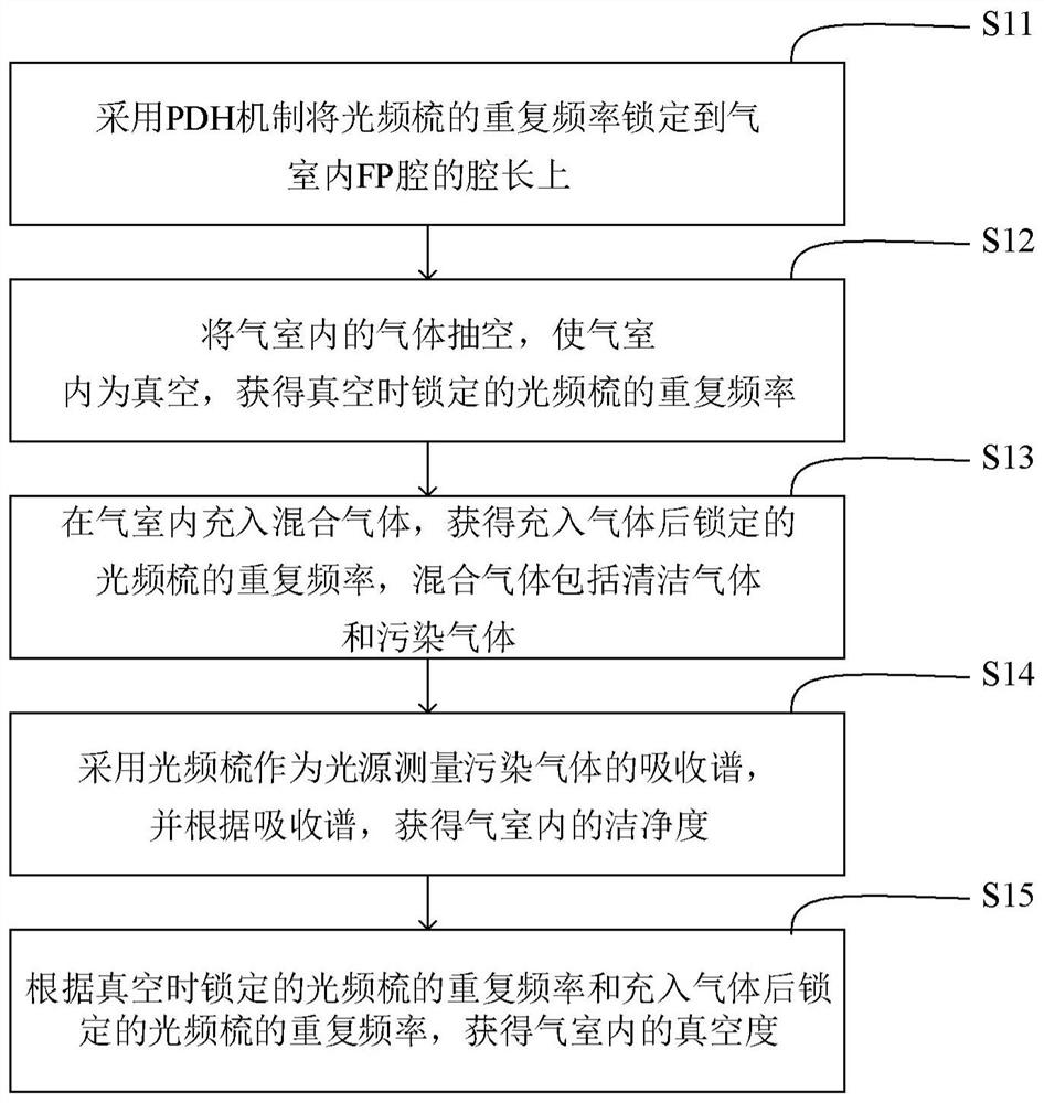
[0046] According to one aspect of the present invention, a vacuum measurement method based on light frequency comb is provided, such as figure 1 shown, including:

[0047] S11, use the PDH mechanism to lock the repeated frequency of the light frequency comb to the cavity length of the FP cavity of the indoor indoor;

[0048] S12, take the gas indoor gas in the gas room, so that the indoor indoor is vacuum, and the repeated frequency of the light frequency comb in the vacuum is obtained;

[0049] S13, fill the hybrid gases indoors, obtain the repeated frequency of the light frequency comb that is locked after the gas is charged.

[0050] S14, uses light frequency comb as a light source to measure the...


PUM


Abstract

The invention provides a vacuum measurement method and device based on an optical frequency comb, belonging to the technical field of vacuum measurement. The vacuum measurement method based on the optical frequency comb includes: using the PDH mechanism to lock the repetition frequency of the optical frequency comb to the cavity length of the FP cavity in the gas chamber; evacuating the gas in the gas chamber to make the gas chamber a vacuum, and obtaining the light locked in the vacuum The repetition frequency of the frequency comb; fill the gas chamber with a mixed gas, and obtain the repetition frequency of the optical frequency comb locked after filling the gas. The mixed gas includes clean gas and polluted gas; the optical frequency comb is used as the light source to measure the absorption spectrum of the polluted gas, And according to the absorption spectrum, the cleanliness of the gas chamber is obtained; according to the repetition frequency of the optical frequency comb locked in vacuum and the repetition frequency of the optical frequency comb locked after filling the gas, the vacuum degree of the gas chamber is obtained. The invention utilizes the wide spectrum characteristic of the optical frequency comb to simultaneously measure the partial pressures of various gas components, and realize the measurement of the cleanliness while measuring the vacuum degree of the vacuum environment.

Description

technical field [0001] The invention relates to the technical field of vacuum measurement, in particular to a vacuum measurement method based on an optical frequency comb. Background technique [0002] Extreme ultravisher, inertial constraints, nuclear fusion countries and long -life vacuum electronic devices have all required the vacuum and cleanliness of the vacuum environment. At present, the monitoring of vacuum environment mostly adopts means such as mass spectrometer and thin film capacitance gauge. In recent years, the physical standards corresponding to many measurement parameters have begun to change to vector standards. Vacuum -based vacuum measurement methods have become research hotspots in the field of vacuum measurement in the field of vacuum measurement. The vacuum measurement methods based on optical means mainly include refractive index measurement and absorption spectrum measurement. The refractive index method adopts continuous single-frequency laser and...

Claims


Application Information

Patent Timeline
Patent Type & Authority Patents(China)
IPC IPC(8): G01L21/00
CPCG01L21/00
Inventor 石俊凯周维虎黎尧陈晓梅刘立拓吴晓斌王魁波王宇
Owner INST OF MICROELECTRONICS CHINESE ACAD OF SCI
Why Eureka
Try Eureka