A tire inner quality detection device

A detection device and quality technology, which is applied in the field of tire production, can solve the problems of inconvenient inspection personnel sampling tires, etc., and achieve the effect of easy promotion and use, reasonable design and compact structure

Active Publication Date: 2020-12-11
JIANGSU TOPOWER WHEEL
View PDF9 Cites 2 Cited by
  • Summary
  • Abstract
  • Description
  • Claims
  • Application Information

AI Technical Summary

Problems solved by technology

[0004] In view of the problem that the above-mentioned existing tire inner quality detection device is not convenient for inspectors to sample tires, the present invention is proposed

Method used


Image

  • A tire inner quality detection device
  • A tire inner quality detection device
  • A tire inner quality detection device

Examples


Embodiment 1

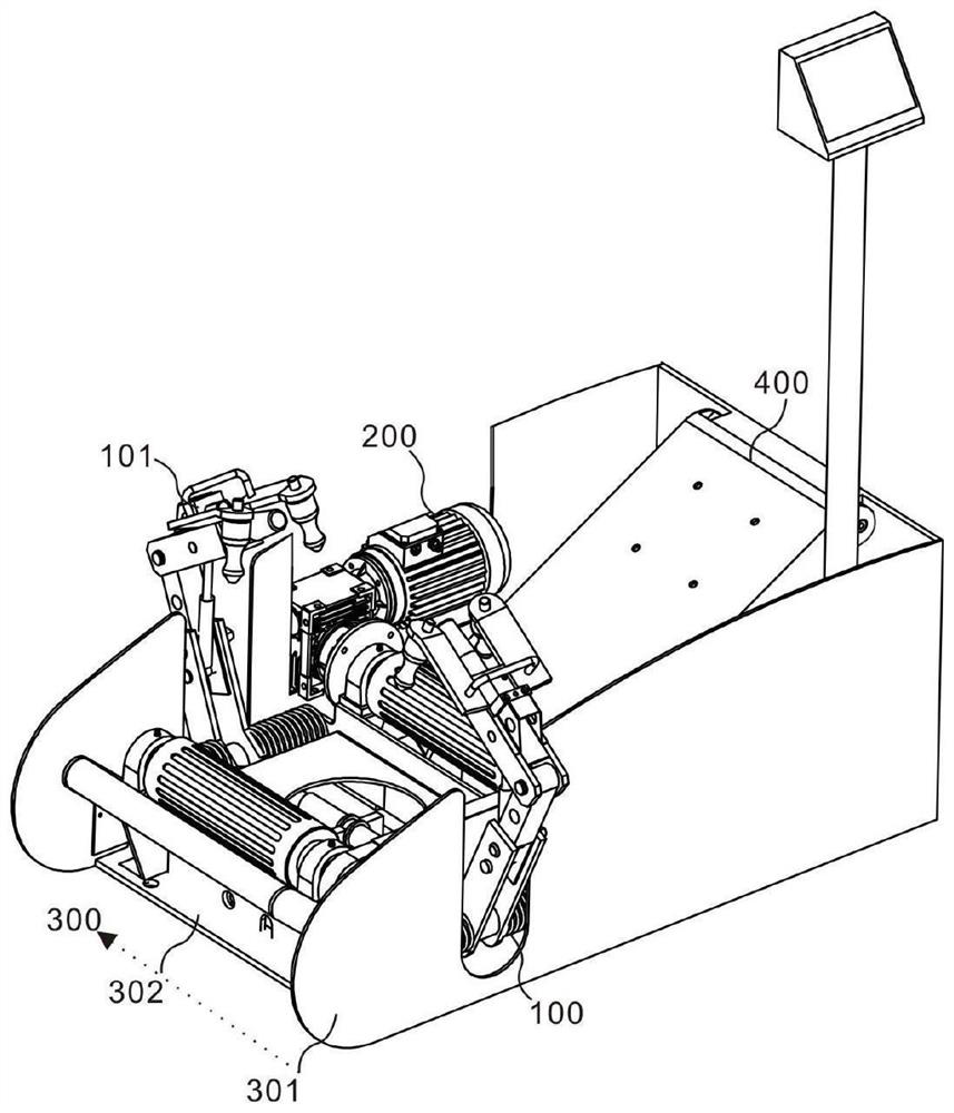
[0048] refer to Figure 1 ~ Figure 3 , which provides a schematic diagram of the overall structure of a tire inner quality detection device, such as figure 1, a tire inner quality detection device includes a pulling unit 100, including a first pulling assembly 101, a second pulling assembly 102 and a two-way hydraulic cylinder 103, and the two ends of the two-way hydraulic cylinder 103 are connected to the first pulling assembly 101 and the two-way hydraulic cylinder 103 respectively. The second pulling assembly 102 is connected, and the first pulling assembly 101 and the second pulling assembly 102 are arranged symmetrically; the driving rotation unit 200 includes a rolling driving assembly 201 and a rolling assembly 202 connected with the rolling driving assembly 201, and the rolling assembly 202 Arranged in parallel with the two-way hydraulic cylinder 103; the bearing unit 300 includes an outer shell 301 and a supporting shell 302, the pulling unit 100 and the rolling assem...

Embodiment 2

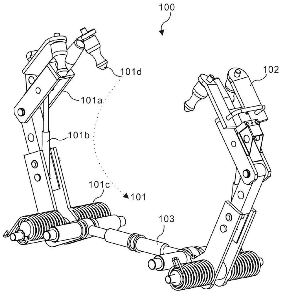
[0055] refer to Figure 6 , This embodiment is different from the first embodiment in that the structure of the first pulling assembly 101 is the same as that of the second pulling assembly 102, and the first pulling assembly 101 includes a linkage 101a, a linkage driving element 101b, a support The part 101c and the claw 101d can pull out the inner side of the tire through the mutual cooperation between the linkage 101a, the linkage drive 101b, the support 101c and the claw 101d, which is convenient for inspection personnel to detect, saving time and effort. Specifically, the structure of the first pull assembly 101 is the same as that of the second pull assembly 102, the first pull assembly 101 includes a linkage 101a, a linkage drive 101b, a support 101c and a claw 101d, and the linkage drive 101b The two ends of the link 101a are respectively connected to the first connecting arm 101a-1 and the second connecting arm 101a-2, and the pulling claw 101d is arranged on the seco...

Embodiment 3

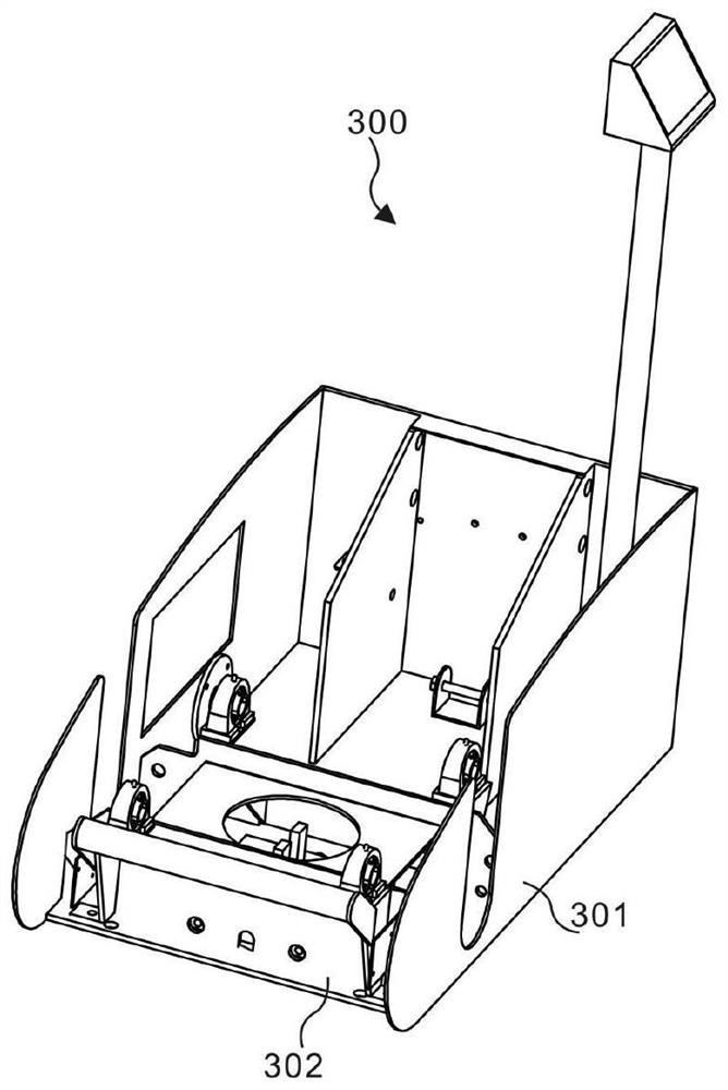
[0060] refer to Figure 7 and 8 This embodiment is different from the above embodiments in that: the lifting unit 400 includes a lifting linkage assembly 401 and a lifting driving assembly 402, and the lifting linkage assembly 401 and the lifting driving assembly 402 are arranged to cooperate with each other to drive the supporting shell 302 to lift , so that the unplugging unit 100 can be realized, and the lifting and lowering of the driving rotation unit 200 can be realized, thereby providing conditions for adapting to testing personnel of different heights, and greatly increasing the practical performance of testing. Specifically, the lifting unit 400 includes a lifting linkage assembly 401 and a lifting drive assembly 402. The ends are respectively connected to the support plate 302e and the second bottom plate 301b of the outer shell 301.

[0061] Further, the lifting linkage assembly 401 includes a linkage cover 401a, a first shaft group 401b, a second shaft group 401c...


PUM


Abstract

The invention discloses a tire inner side quality detecting device. The device comprises a pulling unit, a driving rotation unit, a bearing unit and a lifting unit; the pulling unit comprises a firstpulling assembly, a second pulling assembly and a two-way hydraulic oil cylinder, the two ends of the two-way hydraulic oil cylinder are connected with the first pulling assembly and the second pulling assembly respectively, and the first pulling assembly and the second pulling assembly are symmetrically arranged; the driving rotation unit comprises a rolling driving assembly and a rolling assembly connected with the rolling driving assembly, and the rolling assembly is parallel to the two-way hydraulic oil cylinder; the bearing unit comprises an outer shell and a supporting shell; the two ends of the lifting unit are connected with the outer shell and the supporting shell respectively. According to the tire inner side quality detecting device, through the arrangement and cooperation of the pulling unit, the driving rotation unit, the bearing unit and the lifting unit, the inner wall of a tire can be automatically pulled, so that inspection personnel conveniently conduct sampling inspection on the quality of the tire, and meanwhile the height of the tire can be adjusted according to the inspection comfort of the inspection personnel.

Description

technical field [0001] The invention relates to the technical field of tire production, in particular to a tire inner quality detection device. Background technique [0002] Tires are circular elastic rubber products that are rolled on the ground and rolled on various vehicles or machinery. Usually installed on metal rims, it can support the body, buffer external impact, realize contact with the road surface and ensure the driving performance of the vehicle. Tires are often used under complex and harsh conditions, and they are subjected to various deformations, loads, forces, and high and low temperature effects during driving, so they must have high load-bearing performance, traction performance, and cushioning performance. At the same time, it is also required to have high wear resistance and flex resistance, as well as low rolling resistance and heat generation. Half of the world's rubber consumption is used for tire production, which shows the ability of tires to consu...

Claims


Application Information

Patent Timeline
Patent Type & Authority Patents(China)
IPC IPC(8): G01M17/02
CPCG01M17/02G01M17/021
Inventor 王恒宜刘艮春李俊荣
Owner JIANGSU TOPOWER WHEEL
Why Eureka
Try Eureka