

High-temperature in-situ loading stress measuring device for neutron diffraction
A technology of stress measurement and in-situ addition, which is applied to measuring devices, using stable tension/pressure to test the strength of materials, instruments, etc., can solve the problem of inaccurate stress and strain measurement results, inconvenient dynamic observation, and no consideration of creep effects etc. to achieve the effects of optimizing creep test measurement, improving angle range, and simplifying overall size and weight
Pending Publication Date: 2019-11-05
CENT OF EXCELLENCE FOR ADVANCED MATERIALS +1
View PDF1 Cites 3 Cited by
- Summary
- Abstract
- Description
- Claims
- Application Information
AI Technical Summary
Problems solved by technology
The invention patent (Patent No.: 201510872056.0) titled "An In-Situ Temperature Loading Device for Neutron Diffraction" discloses an in-situ temperature loading device for neutron diffraction. The heating method of the device adopts the furnace cavity Resistance wire heating, large volume, complex structure, and inconvenient dynamic observation of sample heating conditions; in addition, this device does not consider the creep effect of the sample itself under long-term high-temperature loading, which will cause inaccurate stress and strain measurement results
Method used
View moreImage
Smart ImageViewing Examples

Examples
Embodiment approach
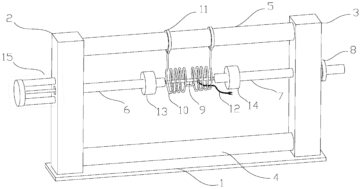
[0028] Such as figure 1 and figure 2 As shown, this embodiment discloses a high-temperature in-situ loading stress measurement device for neutron diffraction.
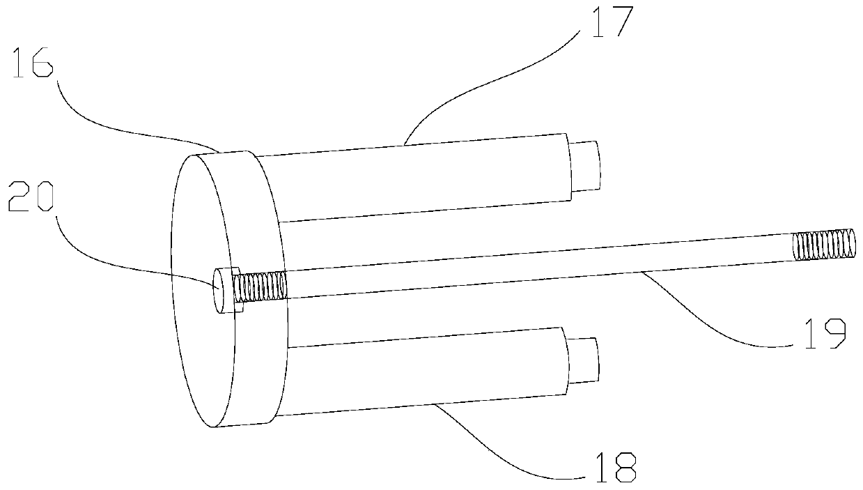
[0029] The device is mainly composed of the following four parts, a support frame, a mechanical stretching component, a heating component and a sample connecting rod component 15 .
[0030] The support frame includes a base 1, a left column 2, a right column 3 and a connecting shaft, wherein the connecting shaft in this embodiment includes an upper connecting shaft 5 and a lower connecting shaft 4, and all components are preferably made of high-strength alloy materials and passed through Welded fixed connections to ensure overall stability of the unit.
Login to View More PUM
 Abstract
The invention discloses a high-temperature in-situ loading stress measuring device for neutron diffraction. The device comprises a supporting frame, a left loading shaft, a right loading shaft, a heating assembly and a connecting rod; the left and right loading shafts penetrate the left and right sides of the supporting frame respectively, a sample soleplate is formed between the left and right loading shafts, the heating assembly comprises an induction coil which is composed of multiple helical form coils, a neutron scattering space is wound and reserved outside a sample, and the induction coil can heat the sample after being electrified; one end of the connecting rod is detachably connected with the supporting frame, and the other end of the connecting rod is detachably connected with one end of the left loading shaft; and when one end of the right loading shaft bearing an external force, the sample is stretched. The high-temperature in-situ loading stress measuring device is smallerin size and simpler in structure, can conveniently observe the condition of the sample in the experiment process, and can optimize creep flow experiment measurement when the sample is loaded at hightemperature, and further a stress strain measurement result is more accurate.
Description
technical field [0001] The invention relates to a sample environment in-situ loading technology in neutron diffraction applications, in particular to a high-temperature in-situ loading stress measurement device for neutron diffraction. Background technique [0002] Neutron diffraction technology is often used to study the internal microstructure of materials such as residual stress, phase transition, micromechanics, etc. The industries involved include aerospace, rail transit, nuclear energy development, etc. In order to study its material properties more accurately, samples are loaded in situ at high temperature The environment has received more and more attention, and the sample environment is usually composed of a high-temperature furnace and a mechanical extensometer. The invention patent (Patent No.: 201510872056.0) titled "An In-Situ Temperature Loading Device for Neutron Diffraction" discloses an in-situ temperature loading device for neutron diffraction. The heating ...
Claims
Login to View More Application Information
Patent Timeline
 IPC IPC(8): G01N3/18G01N3/06G01N3/02
CPCG01N3/02G01N3/06G01N3/18G01N2203/0017G01N2203/0226G01N2203/0641
Inventor詹霞高建波马艳玲张书彦贡志锋王懿强何雨棋
OwnerCENT OF EXCELLENCE FOR ADVANCED MATERIALS