
Projectile echo simulating device and method for emplacement reconnaissance and fire-directing radar

A technology of echo simulation and simulation device, applied in the field of target simulation, can solve the problems of difficult training and detection organization, high training and detection cost, complicated erection and operation, etc., to reduce the difficulty of training organization, simple device structure, economical and practical Effect

Active Publication Date: 2019-11-05
XIAN UNIV OF POSTS & TELECOMM
View PDF22 Cites 6 Cited by
  • Summary
  • Abstract
  • Description
  • Claims
  • Application Information

AI Technical Summary

Problems solved by technology

[0003] The traditional artillery position reconnaissance and calibration radar training and detection methods have the following disadvantages: (1) a professional artillery shooting range is required, and the training and detection organization is relatively difficult
(2) Need to use artillery and ammunition, the cost of training and testing is too high
However, this method also has many disadvantages
One is that the equipment is relatively complicated, and it is necessary to establish a signal channel between the radar and the microwave signal source, and the erection operation is relatively cumbersome. Angle) there is a big difference
Therefore, this method is still rarely used

Method used


Image

  • Projectile echo simulating device and method for emplacement reconnaissance and fire-directing radar
  • Projectile echo simulating device and method for emplacement reconnaissance and fire-directing radar
  • Projectile echo simulating device and method for emplacement reconnaissance and fire-directing radar

Examples


Embodiment Construction

[0038] Attached below Figure 1-4 , a specific embodiment of the present invention will be described in detail, but it should be understood that the protection scope of the present invention is not limited by the specific embodiment.

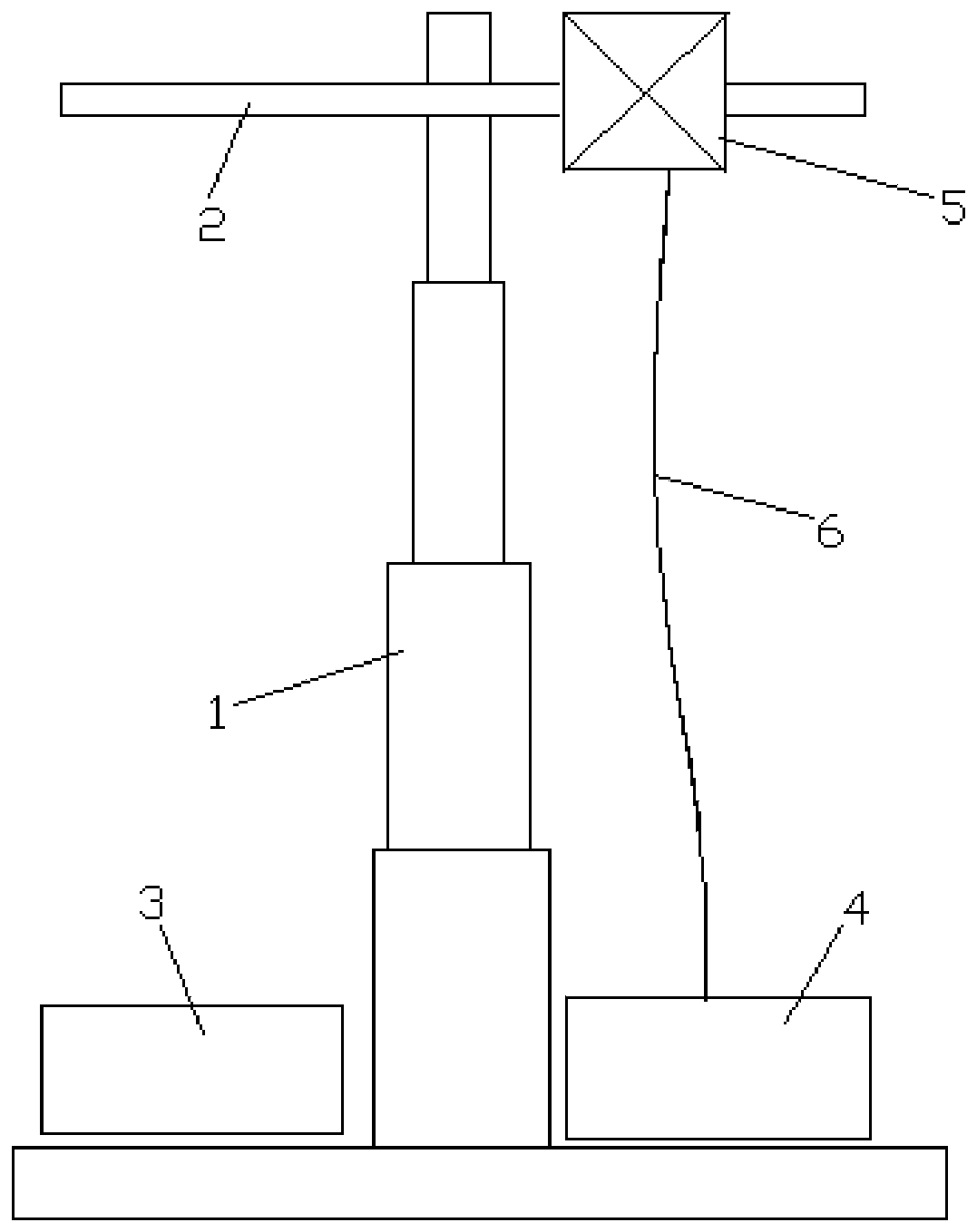
[0039] see figure 1 The simulation device of the present invention consists of a transceiver antenna 5, a digital storage frequency microwave delay circuit 4, a lifting device 1, a lateral movement device 2, a servo and synchronous control device 3, and a microwave cable 6 for connecting the transceiver antenna and the microwave delay circuit 4, etc. composition.

[0040] Wherein the transceiver antenna 5 is responsible for receiving the microwave signal emitted by the radar, and sending the delayed microwave signal for the radar to receive;

[0041] The digital frequency storage microwave delay circuit 4 is responsible for performing real-time delay processing on the received microwave signal emitted by the radar according to the requirements...


PUM


Abstract

The invention relates to the technical field of target simulating, and discloses a projectile echo simulating device and method for an emplacement reconnaissance and fire-directing radar. The simulating device comprises a lifting device, a transverse moving device, a servo and synchronous control device, a digital radio frequency memory microwave delay circuit, a transceiving antenna and a microwave cable. The transverse moving device is horizontally arranged at the upper portion of the lifting device. The transceiving antenna is installed on the transverse moving device and can horizontally move under the control of the transverse moving device. The digital radio frequency memory microwave delay circuit is connected with the transceiving antenna through the microwave cable. The lifting device, the transverse moving device and the digital radio frequency memory microwave delay circuit are connected with the servo and synchronous control device through signals. By means of the projectile echo simulating device and method for the emplacement reconnaissance and fire-directing radar, the problem is solved that the emplacement reconnaissance and fire-directing radar is difficult to train and organize and high in training cost, and meanwhile the problem is solved that projectile trajectory echoes simulated by a simulating device in an existing emplacement reconnaissance and fire-directing radar are unreal.

Description

technical field [0001] The invention relates to the technical field of target simulation, in particular to a projectile echo simulation device and simulation method for a gun position reconnaissance and calibration radar. Background technique [0002] The artillery position reconnaissance and calibration radar is to determine the position of the enemy artillery position or the impact point of our artillery by detecting the flight trajectory of the artillery shells fired by the enemy or our artillery. The daily training method of the artillery position reconnaissance and calibration radar is to set up a radar position in the artillery range, and use the radar to detect the trajectory of the artillery shells for training. In addition, the gun position reconnaissance and calibration radar also needs to detect the working status and detection accuracy of the radar by detecting the shells fired by the artillery after maintenance. [0003] The traditional artillery position recon...

Claims


Application Information

Patent Timeline
IPC IPC(8): G01S7/40G09B9/54
CPCG01S7/4052G09B9/54
Inventor 周文佳
Owner XIAN UNIV OF POSTS & TELECOMM
Learn More