
Lightweight thermal control support structure of space-borne antenna and space-borne antenna

A space-borne antenna and support structure technology, applied in the directions of antenna supports/installation devices, antennas, and antenna components, etc., can solve the problems of increasing contact thermal resistance, shortening phase transition time, and small heat exchange area, so as to ensure the overall The effect of strength, compact structure, good support and heat dissipation

Inactive Publication Date: 2019-11-05
BEIJING INST OF RADIO MEASUREMENT
View PDF6 Cites 6 Cited by
  • Summary
  • Abstract
  • Description
  • Claims
  • Application Information

AI Technical Summary

Problems solved by technology

However, this design is not integrated with the antenna structure, and can only be screwed to the heat source, which not only weighs a lot, but also increases the contact thermal resistance. At the same time, its lattice structure is a traditional cylindrical structure, and the heat transfer area is small, which limits its Further shortening of phase transition time

Method used


Image

  • Lightweight thermal control support structure of space-borne antenna and space-borne antenna
  • Lightweight thermal control support structure of space-borne antenna and space-borne antenna
  • Lightweight thermal control support structure of space-borne antenna and space-borne antenna

Examples


Embodiment 1

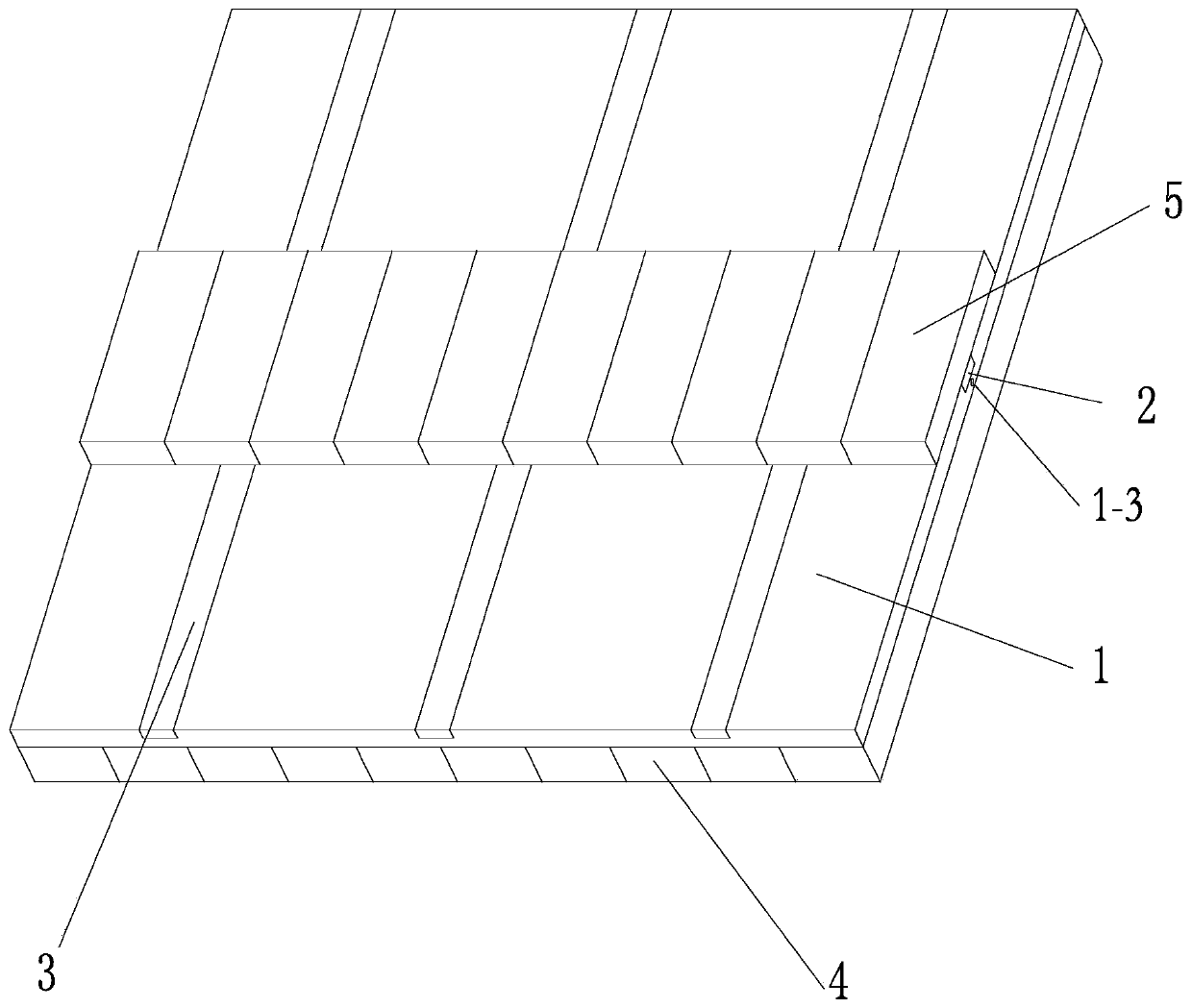
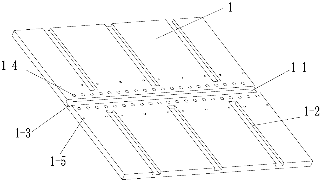
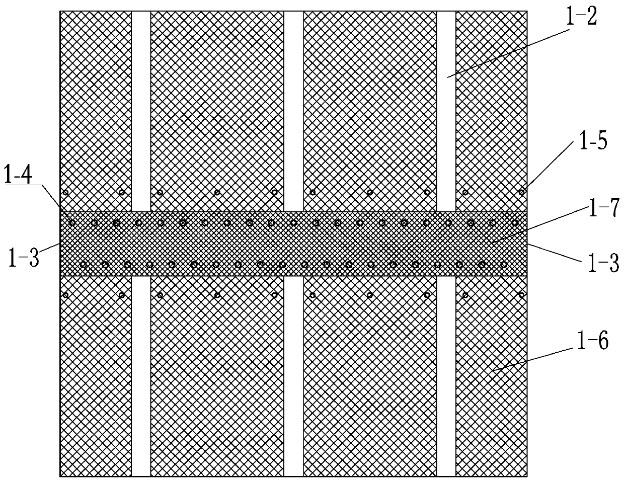
[0032] Such as Figure 1-Figure 5 As shown, a light-weight thermal control support structure of a spaceborne antenna in this embodiment includes a load-bearing heat sink 1 for connecting with the antenna unit 4 and the TR module 5 on both sides, and the load-bearing heat sink 1 has a The hollow structure of the lattice structure 1-7-1, wherein the hollow structure is divided into a phase change material filling lattice area 1-7 and an outer lattice area 1-6, and the phase change material filling lattice area 1 -7 is set corresponding to the TR module 5 .

[0033] Wherein, the load-bearing heat sink 1 is an integral aluminum alloy structure manufactured by laser selection and melting additives, its outer surface is a closed surface with a wall thickness of 0.3-1 mm, and its interior is a spatial lattice structure composed of columnar structures.

[0034] Specifically, reinforcing ribs are provided inside the hollow structure of the heat dissipation plate 1, and the ribs can se...

Embodiment 2

[0047] Such as figure 1 As shown, a space-borne antenna in this embodiment includes the support structure, the antenna unit 4 and the TR module 5, and the TR module 5 and the antenna unit 4 are respectively installed on two sides opposite to the bearing heat dissipation plate 1. On the side, the horizontal heat pipe 3 is installed in the horizontal heat pipe installation groove 1-2, and the vertical heat pipe 2 is installed in the vertical heat pipe installation groove 1-1.

[0048] The space-borne antenna of this embodiment integrates the phase change device and the antenna array panel, and while ensuring the overall strength, it can also achieve weight reduction and phase change heat dissipation, and has a compact structure.


PUM


Abstract

The invention relates to a lightweight thermal control support structure of a space-borne antenna and the space-borne antenna. The support structure comprises a bearing heat dissipation plate with twosides which are used for being connected with an antenna unit and a TR module. The bearing heat dissipation plate has a hollow structure with a lattice structure inside. The hollow structure is divided into a phase change material filling lattice region and an outer lattice region. The phase change material filling lattice region is corresponding to the TR module. The phase change device and theantenna array panel are integrated into one body and arranged as the bearing heat dissipation plate so that the phase change heat dissipation can be realized while realizing the weight reduction design, the structure is compact and good support and heat dissipation effect for the antenna unit and the TR module can be realized.

Description

technical field [0001] The invention relates to an antenna support structure, in particular to a lightweight thermal control support structure of a space-borne antenna and the space-borne antenna. Background technique [0002] The array panel of the spaceborne phased array antenna not only needs to provide installation support and heat dissipation path for the antenna unit, but also ensure that the temperature uniformity among the units and the thermal deformation of the real panel do not exceed the design requirements. The antenna array panel is usually designed as an aluminum honeycomb sandwich structure to reduce weight while ensuring the rigidity of the antenna. Since the start-up time of the antenna is short when it is working in orbit, phase change materials are often used for auxiliary thermal control. The traditional design usually requires the design of a separate phase change module, and machine ribs are often used to increase the contact area of ​​the phase chang...

Claims


Application Information

Patent Timeline
Patent Type & Authority Applications(China)
IPC IPC(8): H01Q1/12H01Q1/00
CPCH01Q1/02H01Q1/12
Inventor 翁俊周红华李培培严洲
Owner BEIJING INST OF RADIO MEASUREMENT
Learn More