
Moisture-proof electric power cabinet based on electric control system

A technology of electrical control system and power cabinet, which is applied in the direction of electrical components, substation/power distribution device shell, substation/switchgear cooling/ventilation, etc. It can solve the problems of moisture ingress, power failure, and power cabinet damp, etc. To achieve the effect of reducing water vapor

Inactive Publication Date: 2019-11-05
PAGMAN TECH (TAICANG) CO LTD
View PDF0 Cites 3 Cited by
  • Summary
  • Abstract
  • Description
  • Claims
  • Application Information

AI Technical Summary

Problems solved by technology

[0003] When the power cabinet is working, a large amount of heat is generated inside, so the power cabinet must be equipped with heat dissipation windows. At present, many power cabinets are used outdoors. Due to the influence of weather factors, external moisture has a great impact on the power cabinet, especially in the early morning and In the middle of the night, moisture can easily enter through the heat dissipation window, causing the interior of the power cabinet to be damp, and then there will be power failures

Method used


Image

  • Moisture-proof electric power cabinet based on electric control system
  • Moisture-proof electric power cabinet based on electric control system
  • Moisture-proof electric power cabinet based on electric control system

Examples


Embodiment 1

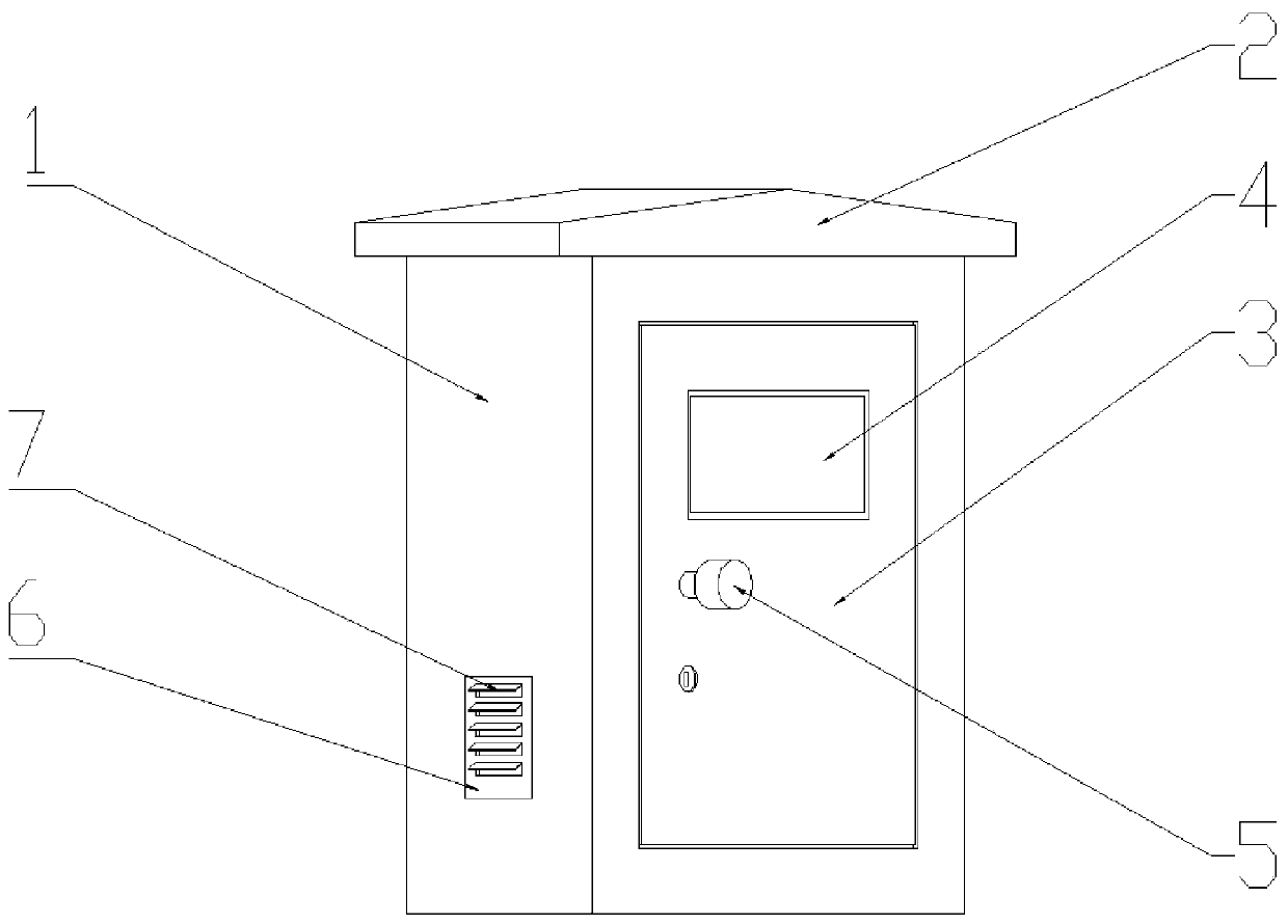
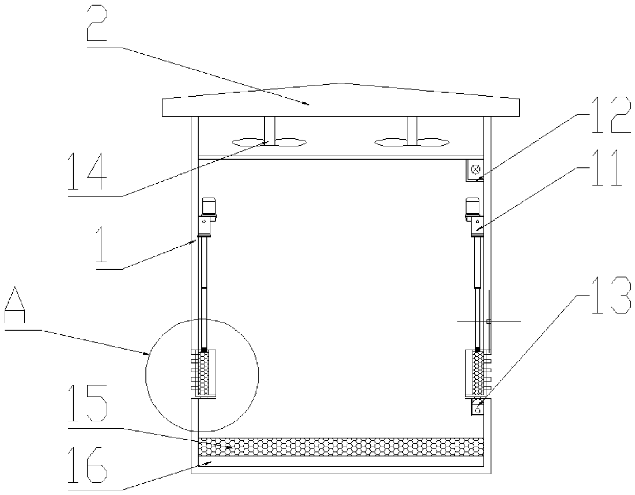
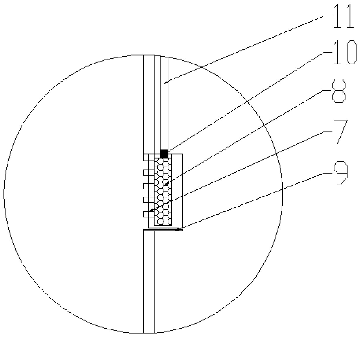
[0035] see Figure 1-5 , a moisture-proof power cabinet based on an electrical control system, including a cabinet body 1 and the main structure of the power cabinet, which play a protective role. The front hinge of the cabinet body 1 is connected with the cabinet door 3, and a window hole is cut on the cabinet door 3, and an observation window 4 is installed in the window hole. The observation window 4 is made of transparent glass, and the cabinet body can be observed through the observation window 4. In the internal situation, the left and right ends of the cabinet body 1 are drilled with ventilation holes 6, and the ventilation holes 6 are provided with U-shaped baffles 7, and the outer ends of the U-shaped baffles 7 are dug with a number of evenly distributed ventilation holes, and the ventilation holes 6 can be installed in the cabinet. When the power facilities in 1 are in operation, heat dissipation is carried out. The lower side of the U-shaped baffle 7 is provided wit...


PUM


Abstract

The invention discloses a moisture-proof electric power cabinet based on an electric control system, and belongs to the technical field of electric power cabinets. The moisture-proof electric power cabinet based on the electric control system comprises a cabinet body, wherein the upper end of the cabinet body is fixedly connected with a top plate, the front end of the cabinet body is hinged with acabinet door, the cabinet door is provided with a window hole, an observation window is installed in the window hole, the left and right ends of the cabinet body are respectively provided with air vents, each air vent is internally provided with U-shaped baffle plates, the outer end of each U-shaped baffle plate is provided with a plurality of uniformly distributed ventilation holes, the lower side of each U-shaped baffle plate is provided with a sliding rail which is fixedly connected with the inner wall of the cabinet body, the upper end of each sliding rail is slidably connected with a sliding block, the sliding block is fixedly connected with the lower end of the corresponding U-shaped baffle plate, the U-shaped baffle plate is inserted with a dehumidification pad, the upper side of the dehumidification pad is provided with an electric push rod, the electric push rod is fixedly connected with the cabinet body, and the mutually approaching ends of the electric push rod and the dehumidification pad are fixedly connected with magnets, thereby being capable of realizing ventilation and heat dissipation, and reducing the moisture in the humid air in the electric power cabinet.

Description

technical field [0001] The invention relates to the technical field of power cabinets, and more specifically, relates to a moisture-proof power cabinet based on an electrical control system. Background technique [0002] The power cabinet is a common power infrastructure with a large number of power components installed inside. The power cabinet is suitable for power plants, petroleum, chemical industry, metallurgy, textiles, high-rise buildings and other industries, as power transmission, power distribution and power conversion. , and with the development of science and technology, most of the current power cabinets are equipped with electrical control modules for auxiliary operation. [0003] When the power cabinet is working, a large amount of heat is generated inside, so the power cabinet must be equipped with heat dissipation windows. At present, many power cabinets are used outdoors. Due to the influence of weather factors, external moisture has a great impact on the p...

Claims


Application Information

Patent Timeline
IPC IPC(8): H02B1/30H02B1/28H02B1/56
CPCH02B1/28H02B1/30H02B1/565
Inventor 王刚唐弇冬周皓
Owner PAGMAN TECH (TAICANG) CO LTD
Learn More