Heat insulating structure body

A technology of structure and thermal insulation material, applied in the direction of protecting pipelines, heat exchange equipment, lighting and heating equipment through thermal insulation, can solve problems such as thickening thermal insulation materials, and achieve lower equipment costs, lower costs, and stable quality. Effect

Inactive Publication Date: 2007-03-07
SANYO ELECTRIC CO LTD
View PDF8 Cites 2 Cited by
  • Summary
  • Abstract
  • Description
  • Claims
  • Application Information

AI Technical Summary

Problems solved by technology

[0003] However, the integrally foamed heat insulating material between the outer surface material and the inner surface material is a material that can achieve higher thermal conductivity than glass fiber in the case of foamed polyurethane with independent cells, so it is suitable for use in warehouses. In the case of the heat insulation box of the freezer at ultra-low temperature (for example, below -90°C), in order to obtain the predetermined heat insulation performance, the thickness of the heat insulation material has to be significantly thickened due to its high thermal conductivity

Method used


Image

  • Heat insulating structure body
  • Heat insulating structure body
  • Heat insulating structure body

Examples


Embodiment 1

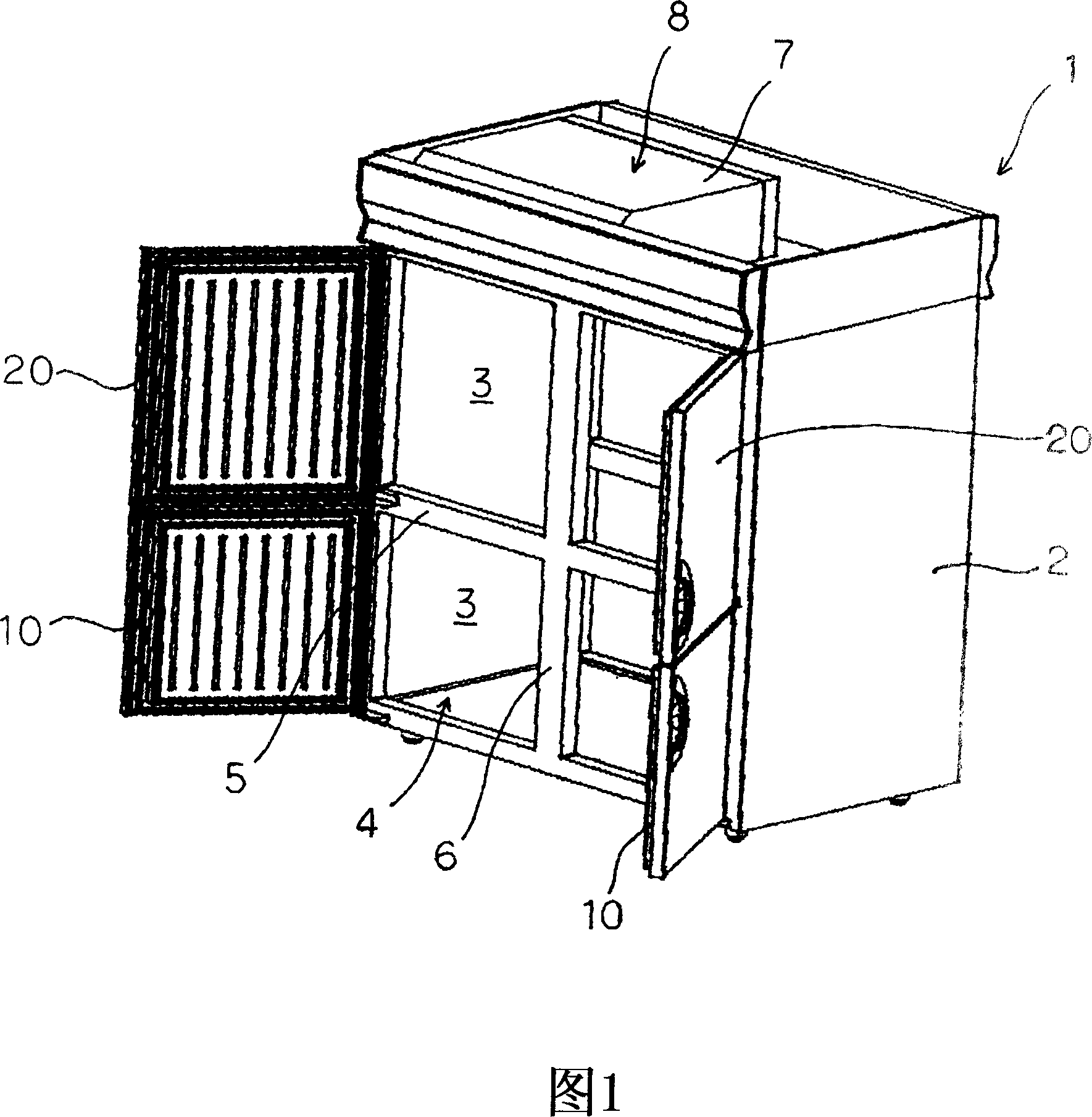
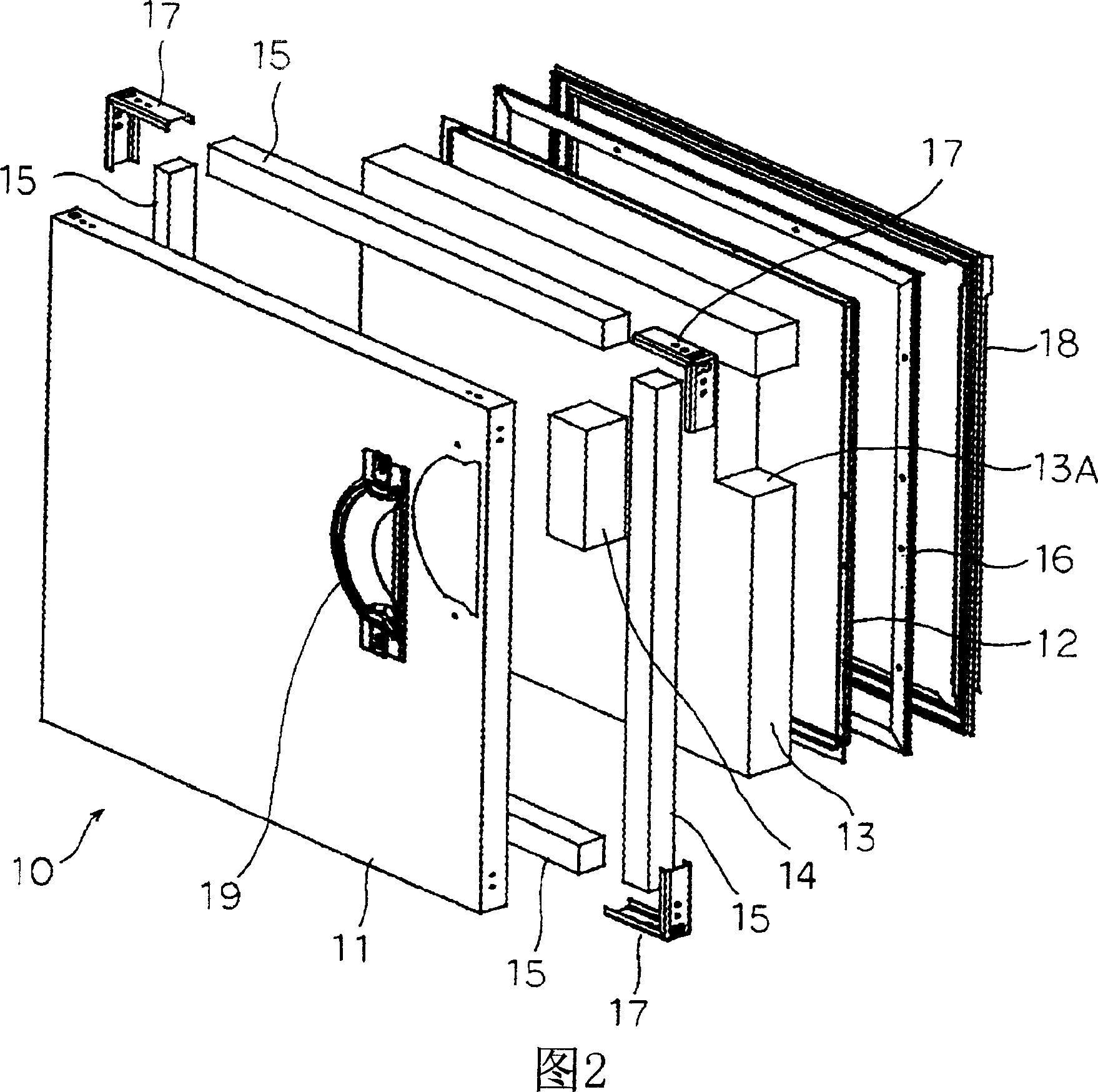
[0037] Next, embodiments of the present invention will be described in detail based on the drawings. Fig. 1 is a perspective view showing a commercial freezer 1 provided with a heat insulating structure according to the present invention, and Fig. 2 is a disassembled perspective view showing an insulating door of the commercial freezer 1 shown in Fig. 1 . The freezer 1 of the embodiment is, for example, a vertical commercial freezer installed in a kitchen of a hotel or a restaurant, and is constituted by a heat insulating box 2 opened at the front.

[0038]The front opening 4 of the storage compartment 3 constituted by the heat insulating box 2 is partitioned into up, down, left, and right at the central portion by an intermediate partition 5 extending in the horizontal direction and a vertical partition 6 extending in the vertical direction. On the left side of the vertical compartment 6, there is a storage room for storing cooked food (cooking) or food materials in the upper...

Embodiment 2

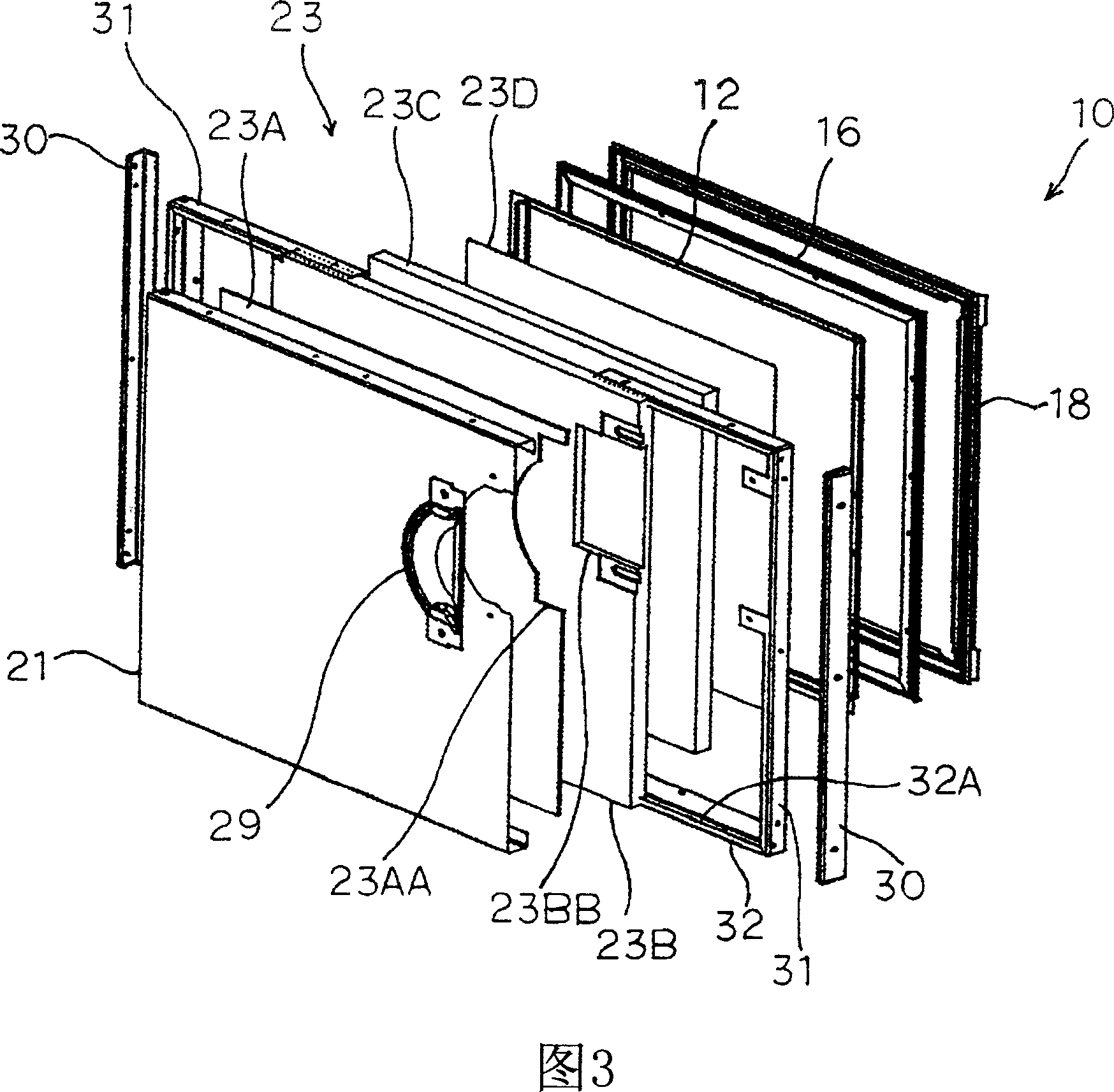
[0053] Fig. 3 is an exploded perspective view showing an insulating door 10 according to another embodiment of the present invention. In addition, the same code|symbol is attached|subjected to the same part as the above-mentioned embodiment, and the description is abbreviate|omitted. In the freezer 1 described with the above-mentioned embodiment, the insulating door 10 is composed of a face material and a heat insulating material 23, wherein the face material is an outer material 21 obtained by bending a steel plate into a U-shaped side surface, and the outer material 21 is formed by closing the outer material. 21 is constituted by a flat plate-shaped inner surface material 12 installed with an opening;

[0054] Both surface materials (the outer surface material 21 and the inner surface material 12 ) are made of the same synthetic resin or steel plate as described above. A handle 29 is provided in the vicinity of the upper part of the outer surface material 21 (on the side of...


PUM


Abstract

The invention provides a heat-insulating structure capable of easily decomposing component materials by kind and reducing equipment cost and production costs. This heat-insulating structure is constituted by a heat-insulating member 13 obtained by sealing a surface of a precast heat-insulating member in a bag capable of preventing the passage of moisture or coating the surface of the precast heat-insulating member with a film capable of preventing the passage of moisture, between face materials. The face materials are composed of an outer face material 11 and an inner face material 12 composing an outer face and an inner face of a heat insulating door 10. The face materials are composed of an outer box and an inner box composing the outer face and the inner face of the heat insulating casing 2.

Description

technical field [0001] The present invention relates to a heat insulating structure equipped with a heat insulating member between surface materials. Background technique [0002] At present, glass fibers or foamed polyurethane with independent cells are used as insulation materials for freezer insulation. Once the glass fibers condense, moisture will be contained inside the heat insulating material, and mold will occur or the heat insulating effect will deteriorate. In addition, since moisture is not contained inside the heat insulating material even if the foamed polyurethane condenses, there is neither generation of mold nor deterioration of the heat insulating effect. When this foamed polyurethane is used for the insulating door 100, as shown in Fig. 4 and Fig. 5, the outer surface material 111 and the inner surface material 112, which are substantially rectangular in length and width, and U-shaped on the side, are combined and formed at both ends respectively. A brake...

Claims


Application Information

Patent Timeline
Patent Type & Authority Patents(China)
IPC IPC(8): F25D23/00F16L59/06F16L59/10
Inventor 棚井健仁
Owner SANYO ELECTRIC CO LTD
Why Eureka
Try Eureka