Supercharge Your Innovation With Domain-Expert AI Agents!

Supercharged floor mopping machine

A floor mopping machine and floor mopping technology, which is applied in the field of floor mopping machines, can solve problems such as increased power consumption, increased weight, and increased costs, and achieve the effects of improving cleaning ability, cleaning effect, and cleaning effect

Active Publication Date: 2019-11-08
平邑仁安中医药产业发展有限公司
View PDF6 Cites 3 Cited by
  • Summary
  • Abstract
  • Description
  • Claims
  • Application Information

AI Technical Summary

Problems solved by technology

[0002] With the continuous improvement of living standards, people's demand and dependence on smart home appliances are increasing. Smart sweepers, moppers, dishwashers, and dryers have begun to appear in family life. These smart home appliances help people clean up. Housework saves a lot of time and strives for relaxation time for the fast-paced urban life; but the current mopping machine still has its obvious shortcomings: the mopping machine needs to remove stubborn stains and dust on the ground. Therefore, it is necessary to maintain a strong drag force when dragging repeatedly. When mopping the floor manually, it is not only necessary to repeatedly drag the mop, but also to press down on the mop to improve its cleaning ability; however, the current mopping machine can only pass through Increase its own weight to increase the pressure of the mop to improve the cleaning ability. This method is relatively crude, which not only increases the weight and cost, but also increases the power consumption, and the cleaning effect achieved is also very small; therefore, the current mopping There are obvious deficiencies in this regard, and it is completely insufficient to help residents improve their lives.

Method used


Image

  • Supercharged floor mopping machine
  • Supercharged floor mopping machine
  • Supercharged floor mopping machine

Examples


Embodiment

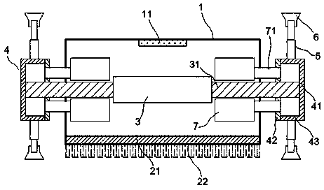
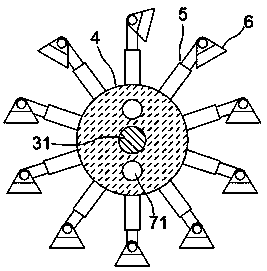
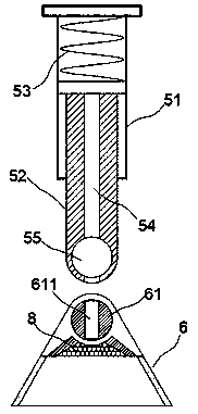
[0015] exist Figure 1 to Figure 4 In the shown embodiment, the pressurized mopping machine includes an organic body 1, a control chip 11 and mopping parts; A mop 22 is provided on the bottom surface of the booster plate 21; a drive motor 3 is installed in the body 1, and the drive shaft 31 of the drive motor 3 stretches out from both sides of the body 1; Disk 4, the booster disk 4 includes a support plate 41, a sealing plate 42 and an annular plate 43, the annular plate 43 is fixedly connected to the supporting plate 41, and the sealing plate 42 and the annular plate 43 are connected by matching annular ribs and annular The chute is slidingly connected; the support plate 41 is fixedly connected with the drive shaft 31, the seal plate 42 is sleeved on the drive shaft 31, and the seal plate 42 can rotate airtightly relative to the drive shaft 31; on the ring plate 43 The booster rod 5 is equidistantly arranged, and the booster rod 5 includes a telescopic rod structure, such as...


PUM


Abstract

The invention relates to a supercharged floor mopping machine. The supercharged floor mopping machine comprises a machine body, a control chip and a floor mopping component, wherein a driving motor isarranged in the machine body; a driving shaft of the driving motor extends out of both sides of the machine body; hollow supercharged disks are arranged at the shaft ends of the driving shaft; the supercharged disks comprise support plates, sealing plates and annular plates; the sealing plates are in slip connection with the annular plates; the support plates are fixedly connected with the driving shaft; the driving shaft is sleeved with the sealing plates; supercharged rods are arranged on the annular plates at equal intervals; a supercharged sucking disk is arranged at the tail end of eachsupercharged rod; air guide channels are formed in the supercharged rods; normally-closed limiting valves are arranged in the supercharged sucking disks; a suction machine is also arranged in the machine body; and an air suction tube of the suction machine is fixedly connected with the sealing plates. Through adoption of the floor mopping machine, the press-fit force between a mop and the ground can be effectively increased; the cleaning capability of the mop for the ground is improved; and the cleaning effect of the floor mopping device is improved effectively.

Description

technical field [0001] The invention relates to an intelligent household appliance, in particular to a floor mopping machine. Background technique [0002] With the continuous improvement of living standards, people's demand and dependence on smart home appliances are increasing. Smart sweepers, moppers, dishwashers, and dryers have begun to appear in family life. These smart home appliances help people clean up. Housework saves a lot of time and strives for relaxation time for the fast-paced urban life; but the current mopping machine still has its obvious shortcomings: the mopping machine needs to remove stubborn stains and dust on the ground. Therefore, it is necessary to maintain a strong drag force when dragging repeatedly. When mopping the floor manually, it is not only necessary to repeatedly drag the mop, but also to press down on the mop to improve its cleaning ability; however, the current mopping machine can only pass through Increase its own weight to increase t...

Claims


Application Information

Patent Timeline
Patent Type & Authority Applications(China)
IPC IPC(8): A47L11/28A47L11/40
CPCA47L11/28A47L11/40A47L11/4036A47L11/4052
Inventor 王丽萍
Owner 平邑仁安中医药产业发展有限公司
Features
  • R&D
  • Intellectual Property
  • Life Sciences
  • Materials
  • Tech Scout
  • Unparalleled Data Quality
  • Higher Quality Content
  • 60% Fewer Hallucinations
Learn More