Pushing cutter rod bending deformation compensation mechanism suitable for stapler

A technology of bending deformation and compensation mechanism, which is applied in the direction of surgical fixation nails, etc., can solve the problems of different front and rear displacements, the limitation of the swing angle of the swing head, and the deformation of the metal sheet deformation, so as to improve the convenience of operation and reduce the firing rate. force effect

Pending Publication Date: 2019-11-08
舒拓 +1
View PDF0 Cites 1 Cited by
  • Summary
  • Abstract
  • Description
  • Claims
  • Application Information

AI Technical Summary

Problems solved by technology

However, in the process of bending and elastic deformation of the pusher rod assembly, the elastic deformation of the two metal sheets on the outside must be inconsistent, resulting in different front and rear displacements of the two, which can easily cause the metal sheet on one side to be inconsistent with the foundation. The movable gap of the block is firstly offset by the displacement, so that the push rod assembly and the basic block are pressed

Method used


Image

  • Pushing cutter rod bending deformation compensation mechanism suitable for stapler
  • Pushing cutter rod bending deformation compensation mechanism suitable for stapler
  • Pushing cutter rod bending deformation compensation mechanism suitable for stapler

Examples


Embodiment Construction

[0024] In the description of the present invention, it should be understood that the orientations or positional relationships indicated by the terms "front", "rear", "left", "right" etc. are based on the orientations or positional relationships shown in the drawings, and are only for It is convenient to describe the present invention and simplify the description, but does not indicate or imply that the device or element referred to must have a specific orientation, be constructed and operate in a specific orientation, and thus should not be construed as limiting the present invention.

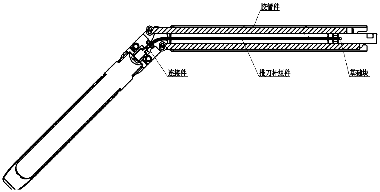
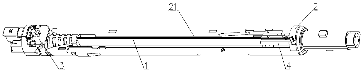
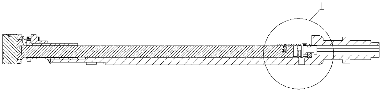
[0025] Below in conjunction with specific embodiment, content of the present invention is described in further detail, figure 2 It shows a three-dimensional schematic view of the pusher rod bending deformation compensation mechanism suitable for an anastomat in the present invention, which is mainly composed of a pusher rod assembly 1, a rubber tube part 2, a connecting part 3 and a basic block...


PUM


Abstract

The invention relates to a pushing cutter rod bending deformation compensation mechanism suitable for a stapler. The pushing cutter rod bending deformation compensation mechanism comprises a pushing cutter rod assembly, a hose part, a connecting part, a base block and a swing block, wherein the connecting part is connected to the left end of the pushing cutter rod assembly, the hose part slidablysleeves the base block to push the pushing cutter rod assembly to move in the axial direction of the hose part, and the swing block is composed of a mounting portion and a compensation function portion; the mounting portion is freely and rotatably arranged on the base block in an inserted mode, an inserting slot is formed in the pushing cutter rod assembly for accommodating the compensation function portion; and thus, when the head swing motion of a jaw occurs, the connecting part rotates correspondingly, at the same time, internal bending elastic deformation of the pushing cutter rod occurs,so that the swing block is driven to perform an adaptive rotational motion about the central axis of the swing block, the situation that the pushing cutter rod assembly abuts against tightly relativeto the base block is avoided, smooth progress of the jaw swing movement is ensured, and the firing force required by an instrument is reduced.

Description

technical field [0001] The invention relates to the technical field of stapler manufacturing, in particular to a bending deformation compensation mechanism of a pusher bar suitable for a stapler. Background technique [0002] In laparoscopic surgery and thoracoscopic surgery, laparoscopic cutting stapler is usually used for cutting and anastomosis of esophagus, stomach, duodenum, small intestine, colon, rectum, appendix, gallbladder, pancreas and spleen in the digestive tract, It is also used in cutting and anastomotic operations such as the lung and trachea in the respiratory tract, and in the bladder and uterus in the urogenital system. Through its application, it can greatly reduce the surgical wound, shorten the operation time and improve the quality of the operation. [0003] In actual use, in order to ensure the accuracy of the position of the jaw relative to the diseased tissue and improve the convenience of the operation, the doctor needs to adaptively swing the head...

Claims


Application Information

Patent Timeline
IPC IPC(8): A61B17/072
CPCA61B17/07207A61B2017/07221A61B2017/07285
Inventor 舒拓
Owner 舒拓
Why Eureka
Try Eureka