
Oxygen respirator with novel ventilation structure

A ventilation structure and respirator technology, applied in the direction of respiratory protection devices, fire rescue, life-saving equipment, etc., can solve the problems of being easily affected by environmental factors such as temperature and collision, and insufficient work stability, so as to avoid the influence of deformation and equipment Stabilizing, reducing impact effects

Active Publication Date: 2019-11-08
ZHEJIANG HENGTAI SAFETY EQUIP
View PDF12 Cites 4 Cited by
  • Summary
  • Abstract
  • Description
  • Claims
  • Application Information

AI Technical Summary

Problems solved by technology

Moreover, they are often connected through plastic pipes, but such connection methods are easily affected by environmental factors such as temperature and collision, resulting in insufficient work stability.

Method used


Image

  • Oxygen respirator with novel ventilation structure
  • Oxygen respirator with novel ventilation structure
  • Oxygen respirator with novel ventilation structure

Examples


Embodiment 1

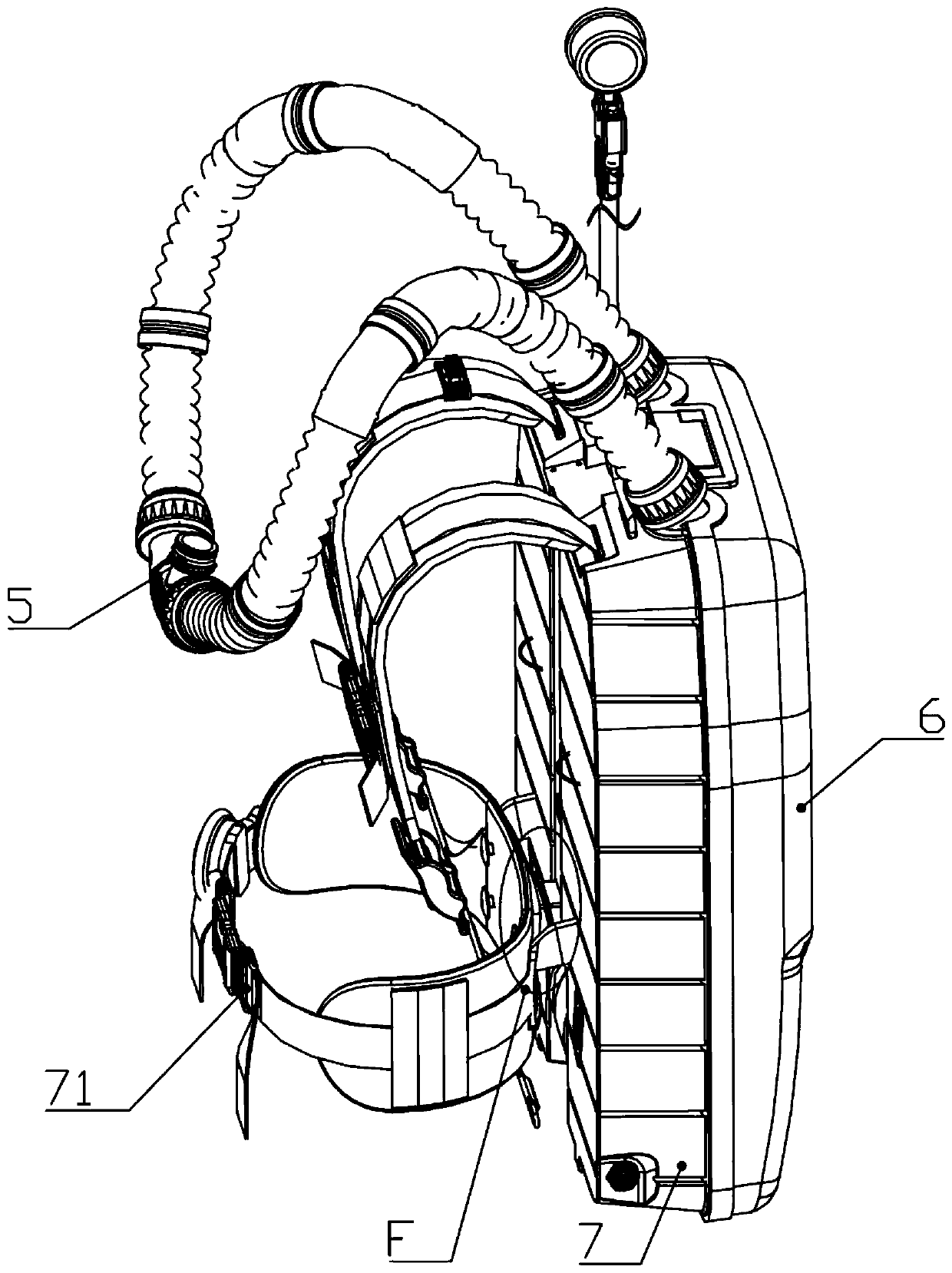
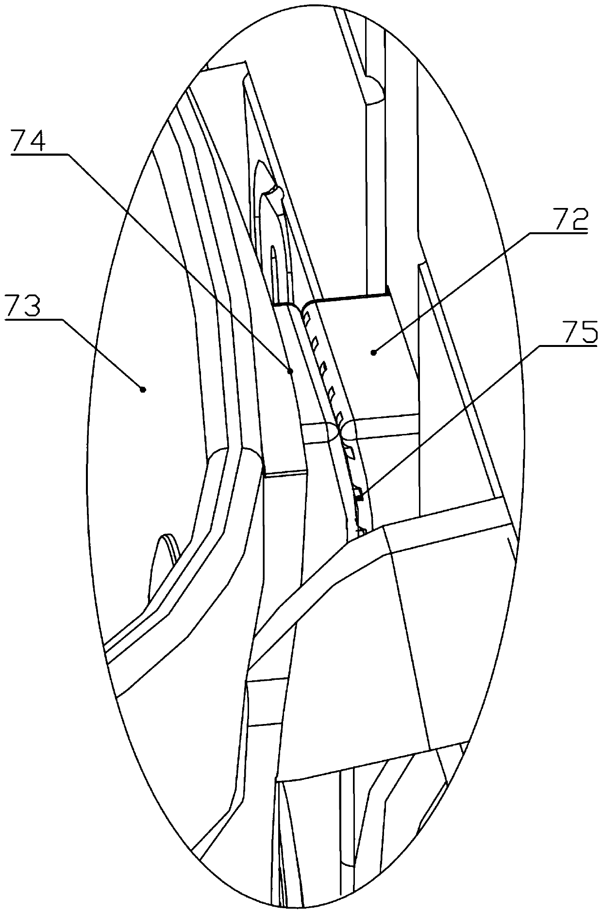
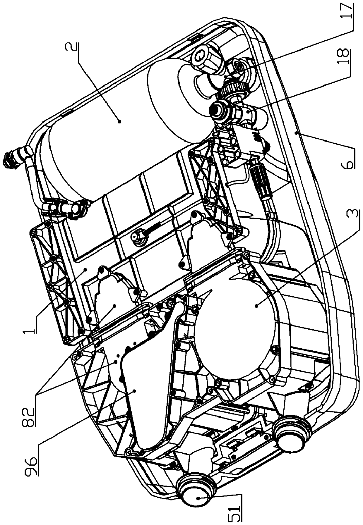
[0044] Embodiment one: if Figure 1-15 As shown, an oxygen respirator includes a respirator main body; The technical solution specifically discloses a structural form of an oxygen respirator.

[0045] 2 Preferably, a clean tank storage area is formed in the main body of the respirator, and the clean tank 4 is detachably arranged in the clean tank storage area; the main body of the respirator also includes a breathing valve assembly 5, and the breathing valve assembly 5 and The cooling tank 3 and / or the cleaning tank 4 are set independently.

[0046]The technical solution specifically discloses an installation method of the cleaning tank 4 . By independently designing the clean tank 4 in the clean tank storage area, such a design can be quickly disassembled when the clean tank 4 needs to be actually replaced. The main body of the respirator described in this technical solution includes a three-way respirator connected with an air inlet joint 51, and the air inlet joint 51 ne...

Embodiment 2

[0077] Embodiment 2: This technical solution is basically the same as Embodiment 1, the difference is that the connection modes of the air inlet joint 51, the gas flow channel and the clean tank 4 are different. Previously, the gas flow channel was placed on the lower side of the clean tank 4, and the connection with the gas flow channel was realized by opening a hole at the lower end of the clean tank 4. In the present embodiment, the gas flow path can be connected and sealed with the clean tank 4 and can be realized by connecting the middle nut, that is, there is a threaded section at one end of the gas flow path, and the clean tank 4 also has a threaded section, and the two threads are connected by the nut. Changes in position between segments implement connections. Of course, there are many ways to realize the connection between the gas flow channel and the clean tank 4, and only two of them are specifically described here.


PUM


Abstract

The invention discloses an oxygen respirator with a novel ventilation structure, and belongs to the technical field of emergency rescue equipment. The oxygen respirator with the novel ventilation structure comprises a respirator main body, wherein the respirator main body at least comprises an air bag assembly, an oxygen tank, a cooling tank and a cleaning tank; the outer end of the air bag assembly is provided with an air bag body; a plurality of air vents are formed in the lower end of the air bag body; and the lower end of the cooling tank and / or the cleaning tank communicates with the airvents. According to the technical scheme, a structural design that the ventilation structure is arranged at the lower portions of the tank bodies, such as the oxygen tank, the cooling tank, the cleaning tank, is specifically disclosed. Through the structure design, the influence caused by the impact can be avoided, besides, the traditional way by connecting pipelines for ventilation is abandoned,and ventilation is directly carried out by the air vents formed in the lower end of the air bag body, so that the deformation influence of the impact on the pipelines is further avoided, the influenceof temperature on the ventilation structure is reduced, and the whole equipment is more stable and assembly is simpler and more convenient.

Description

technical field [0001] The invention belongs to the technical field of emergency rescue equipment, in particular to an oxygen respirator with a novel ventilation structure. Background technique [0002] At present, oxygen respirators are also called isolated compressed oxygen respirators. The respiratory system is isolated from the outside world. The instrument and the human respiratory system form an internal circulation. Oxygen is provided by high-pressure cylinders, and airbags are used to store the gas during exhalation and inhalation. It was introduced from the former Soviet Union in the 1950s and has been produced for decades. It has a large quantity and a wide range. Respiratory protection products, with stable and reliable performance, are widely used in industries (departments) such as petroleum, chemical industry, metallurgy, coal, mines, laboratories, etc., for specially trained personnel to carry out emergency rescue and accidents in toxic and harmful gas environ...

Claims


Application Information

Patent Timeline
Patent Type & Authority Applications(China)
IPC IPC(8): A62B7/04A62B9/02
CPCA62B7/04A62B9/02
Inventor 柯高峰
Owner ZHEJIANG HENGTAI SAFETY EQUIP
Learn More