
High-energy beam welding method for dual-metal layered composite board

A high-energy beam welding, bimetallic layered technology, applied in electron beam welding equipment, welding equipment, laser welding equipment and other directions, can solve the problems of affecting the comprehensive performance of joints, serious dilution of composite plates, etc., and achieve a wide range of industrial application prospects and processes. Simple assembly and high joint performance

Active Publication Date: 2019-11-08
SHENYANG AEROSPACE UNIVERSITY
View PDF10 Cites 0 Cited by
  • Summary
  • Abstract
  • Description
  • Claims
  • Application Information

AI Technical Summary

Problems solved by technology

[0006] Aiming at the deficiencies in the prior art, the present invention provides a high-energy beam welding method for bimetallic laminated composite panels, which solves the serious dilution of double-plates in the single-sided welding and double-sided forming of bimetallic laminated composite panels in the existing high-energy beam welding technology , The problem that obviously affects the comprehensive performance of the joint has the advantages of significantly reducing the dilution rate of the doubler plate and improving the joint performance of the metal layered composite plate without processing the groove

Method used


Image

  • High-energy beam welding method for dual-metal layered composite board
  • High-energy beam welding method for dual-metal layered composite board
  • High-energy beam welding method for dual-metal layered composite board

Examples


Embodiment 1

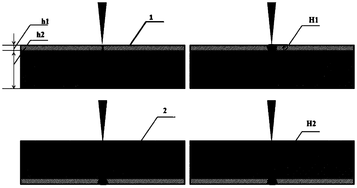
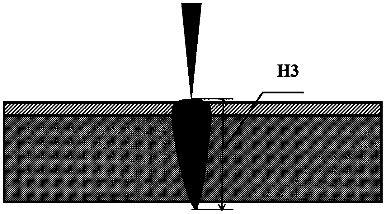
[0027] Such as figure 1 As shown, a kind of 6.0mm thick aluminum-copper bimetallic laminated board is welded by the high energy beam welding method of a kind of bimetallic laminated composite board of the present invention, wherein the thickness h2 of the aluminum substrate is 4.8mm, and the thickness h1 of the copper clad board 1.2mm, the high-energy beam heat source adopts electron beam to carry out welding in the present embodiment, specifically comprises the following steps:

[0028] Step 1: Preparing for High Energy Beam Welding

[0029] Remove the dust and oil on the joint surface of the composite board, and keep the joint surface clean;

[0030] Step 2: Welding of copper composite board in aluminum-copper composite board

[0031] The aluminum-copper composite boards to be welded are tightly butt-jointed, and the side of the doubler board 1 faces the high-energy beam heat source, and then the high-energy beam heat source is used to weld it to realize the welding of the...


PUM


Abstract

A high-energy beam welding method for a dual-metal layered composite board includes the following steps that (1) the material of the to-be-welded dual-metal layered composite board, the thickness h1 of a compounding board and the thickness h2 of a base board are determined, dust and oil stains on butt-joint surfaces of the composite board are removed, and the cleanliness of the butt-joint surfacesis maintained; (2) the to-be-welded composite board is subjected to butt-joint assembling and welded through a high-energy beam heat source, and it is guaranteed that the depth of fusion H1 is greater than or equal to 1.0h1 and less than or equal to 1.15h1; and (3) the composite board with the compounding board welded in the step (2) is overturned and fixed, the base board is welded through the high-energy beam heat source, and it is guaranteed that the depth of fusion H2 is greater than or equal to 0.9h2 and less than or equal to 1.0h2, and the sum of H1 and H2 is less than or equal to h1+h2+0.30mm and greater than or equal to h1+h2+0.01mm, so that high-energy beam welding of the dual-metal layered composite board is completed. The welding method solves the problems that when existing high-energy beam welding technologies are used for single-face welding and double-face forming of dual-metal layered composite boards, compounding boards are seriously diluted and the comprehensive performance of joints is obviously affected, and has the advantages that under the condition of no machining groove, the diluting rate of compounding boards can be obviously lowered and the joint performance of metal layered composite boards is improved.

Description

technical field [0001] The invention belongs to the technical field of high-energy beam welding, and in particular relates to a high-energy beam welding method for a bimetallic layered composite plate. Background technique [0002] Metal layered composite board is a composite structural material prepared by two or more layers of different metal plates through forging, explosive welding, etc. Among them, the thinner board is generally called double board, which is usually more expensive. The main function It is to improve the electrical conductivity, heat conduction, corrosion resistance and other properties of the composite board; the relatively thicker board is called the substrate, and the cost is generally lower. The main function is to reduce the weight of the composite board and improve the strength. Therefore, composite panels often have comprehensive properties that a single metal material does not have, so they have attracted much attention in the automotive, aerospa...

Claims


Application Information

Patent Timeline
IPC IPC(8): B23K10/02B23K26/21B23K15/00
CPCB23K10/02B23K15/00B23K26/21
Inventor 徐荣正李福山国旭明张占伟李孝峰康宏达李智
Owner SHENYANG AEROSPACE UNIVERSITY
Learn More