Coaxial double-blade gas isolation seal device

A technology of sealing device and gas isolation, which is applied to parts of pumping devices for elastic fluids, sealing of engines, liquid fuel engines, etc., can solve problems such as large friction and calorific value, wear, and influence on sealing gaps, and achieve Improve the sealing effect and enhance the effect of isolation

Active Publication Date: 2019-11-08
乐清市芮易经济信息咨询有限公司
View PDF7 Cites 0 Cited by
  • Summary
  • Abstract
  • Description
  • Claims
  • Application Information

AI Technical Summary

Problems solved by technology

[0003] These devices need to isolate the medium gas in the device from the external atmosphere, because it is a moving device, and the work needs to use the rotating shaft, and the rotating power of the rotating shaft generally comes from a motor or transmission device outside the device, at the end of the machine It is bound to involve rotating and dynamic sealing, and a sealing ring is directly used to hold the main shaft. Because the dynamic and static parts are in contact, there will be relatively large friction, and the power loss can still be received, but the large amount of heat generated by friction cannot be dissipated in time, and local temperature The rise is very large, which not only affects the sealing gap, but also causes wear and tear, frequent maintenance, and some use liquid seals, let a rotating ring be inserted into an oil chamber, and keep in contact with the oil while rotating, so that the liquid is isolated from both sides Gas, but this method still has a large friction and calorific value, the oil needs to flow and add a heat exchanger, and the power loss on the spindle is also large, and the work efficiency is low

Method used


Image

  • Coaxial double-blade gas isolation seal device
  • Coaxial double-blade gas isolation seal device
  • Coaxial double-blade gas isolation seal device

Examples


Embodiment Construction

[0031] The following will clearly and completely describe the technical solutions in the embodiments of the present invention with reference to the accompanying drawings in the embodiments of the present invention. Obviously, the described embodiments are only some, not all, embodiments of the present invention. Based on the embodiments of the present invention, all other embodiments obtained by persons of ordinary skill in the art without making creative efforts belong to the protection scope of the present invention.

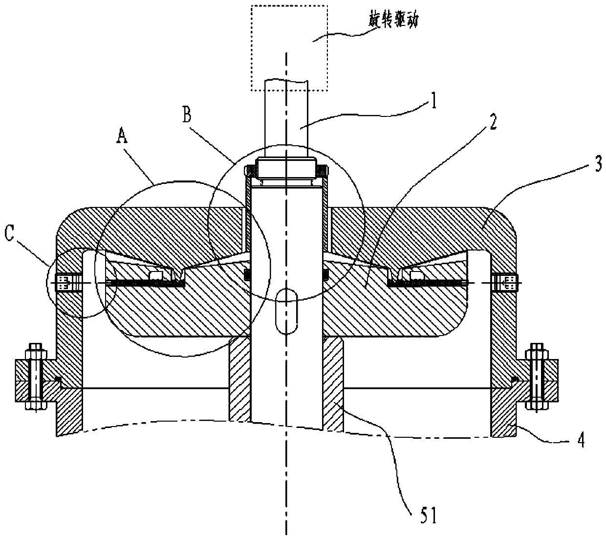
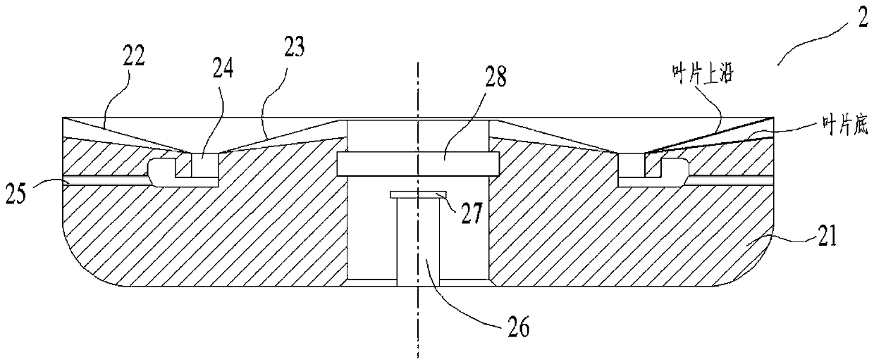
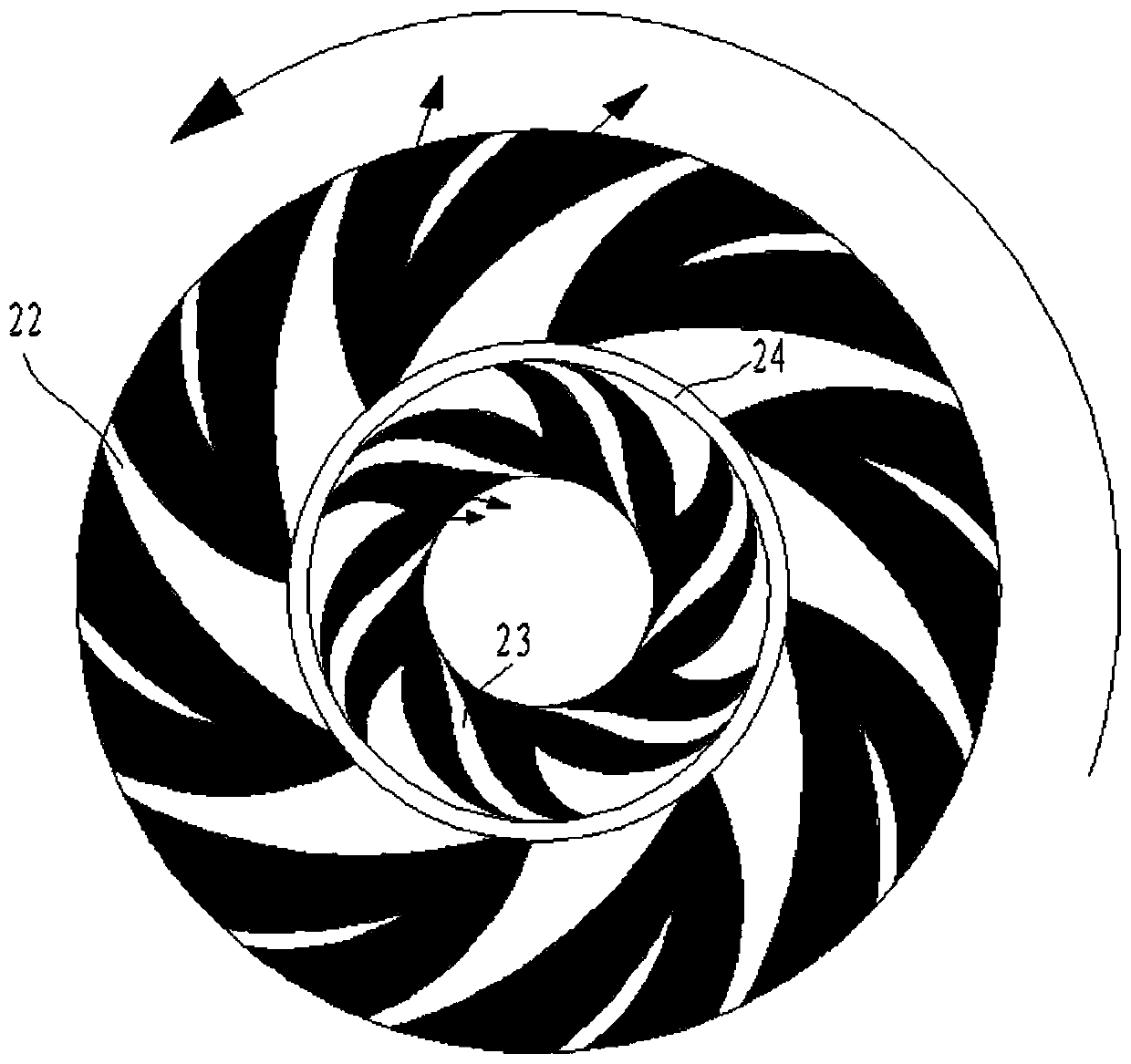
[0032] Such as figure 1 As shown, a coaxial double-blade gas isolation sealing device includes a main shaft 1, a sealing wheel 2, a sealing cover 3 and a housing 4, the sealing cover 3 is arranged at the end of the housing 4, and the main shaft 1 passes through the sealing cover 3 to connect to the outside Driven by rotation, the main shaft 1 is sleeved with a sealing wheel 2, and the sealing wheel 2 is located in the sealing cover 3, such as figure 2 , 3 A...


PUM


Abstract

The invention discloses a coaxial double-blade gas isolation seal device. A main shaft, a seal wheel, a seal cover and a shell are included. The seal cover is arranged at the end portion of the shell,and the main shaft penetrates through the seal cover and is connected with an outer rotation driver. The main shaft is sleeved with the seal wheel, the seal wheel is located in the seal cover and comprises a wheel body, an outer ring blade and an inner ring blade, the outer ring blade and the inner ring blade are arranged on the end face of the side, towards the seal cover, of the wheel body andare annularly distributed with the main shaft as the center, and after the outer ring blade and the inner ring blade are driven by the main shaft to rotate, the outer ring blade conducts centrifugal air pumping, the inner ring blade conducts centripetal air pumping, and the contact face of the wheel body and the main shaft is provided with an O-shaped ring. The main shaft is vertically arranged. The seal wheel further comprises an isolation cavity and a liquid injection hole. The seal cover further comprises a protruding ring arranged on the end face towards the seal wheel, the protruding ringis inserted in the isolation cavity, and seal liquid submerges the bottom of the protruding ring in the static state.

Description

technical field [0001] The invention relates to the field of gas sealing, in particular to a coaxial double-blade gas isolation sealing device. Background technique [0002] Sealing is required on many machines, such as stirring tanks that cannot touch the air medium or volatilized gases that cannot be discharged into the atmosphere in large quantities, or fans that blow some slightly harmful gases. [0003] These devices need to isolate the medium gas in the device from the external atmosphere, because it is a moving device, the work needs to use the rotating shaft, and the rotating power of the rotating shaft generally comes from a motor or transmission device outside the device, at the end of the machine It is bound to involve rotating and dynamic sealing, and a sealing ring is directly used to hold the main shaft. Because the dynamic and static parts are in contact, there will be relatively large friction, and the power loss can still be received. However, a large amount...

Claims


Application Information

Patent Timeline
IPC IPC(8): F16J15/42
CPCF04D17/08F04D29/083F04D29/30
Inventor 葛亮
Owner 乐清市芮易经济信息咨询有限公司
Why Eureka
Try Eureka