

Novel LED lamp with efficient heat dissipation function
Patent Information
- Authority / Receiving Office
- CN · China
- Current Assignee / Owner
- 辽宁海浪防爆电器有限责任公司
- Publication Date
- 2019-11-08
Smart Images
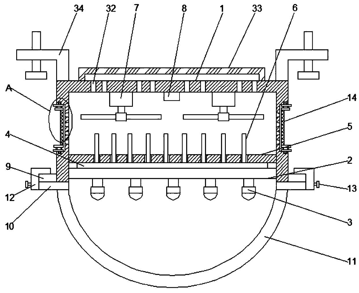
Figure 1 
Figure 2 
Figure 3
Abstract
Description
technical field
[0001] The invention relates to the technical field of LED lamps, in particular to a novel LED lamp with efficient heat dissipation. Background technique
[0002] The LED lamp is an electroluminescent semiconductor material chip, which is cured on the bracket with silver glue or white glue, and then connected to the chip and the circuit board with silver or gold wires, and sealed with epoxy resin around it to protect the inner core wire. Function, the shell is finally installed, so the shock resistance of the LED lamp is good.
[0003] Existing LED lamps tend to generate a lot of heat during long-term use, and it is difficult to discharge the LED lamps in time, causing the LED lamp board to heat up, easily damaging the internal electronic components, and affecting the service life of the LED lamp , In addition, the traditional LED lights are simple in structure, and usually adopt a fixed integrated structure, which is inconvenient for disassembly and mainten...