
A high-efficiency tea dehydration device

A dehydration device and tea technology, which are applied to heating devices, pre-extraction tea treatment, lighting and heating equipment, etc., can solve problems such as unfavorable water vapor emission, and achieve improved dehydration drying speed, drying effect, and dehydration effect. Effect

Active Publication Date: 2020-10-16
金寨县蝠牌茶旅有限公司
View PDF7 Cites 0 Cited by
  • Summary
  • Abstract
  • Description
  • Claims
  • Application Information

AI Technical Summary

Problems solved by technology

However, there are certain technical defects in this patent, such a sealed drying method is not conducive to the release of water vapor

Method used


Image

  • A high-efficiency tea dehydration device
  • A high-efficiency tea dehydration device
  • A high-efficiency tea dehydration device

Examples


Embodiment 1

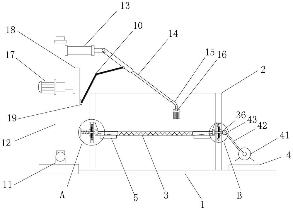
[0027] see figure 1 , a high-efficiency tea dehydration device, including a base plate 1, an operation box 2 is installed on the base plate 1, a dehydration screen 3 is installed horizontally in the operation box 2, and a frame 31 is installed on the four sides of the dehydration screen 3 , The frame 31 is used to limit the tea leaves to prevent the tea leaves from being screened out.

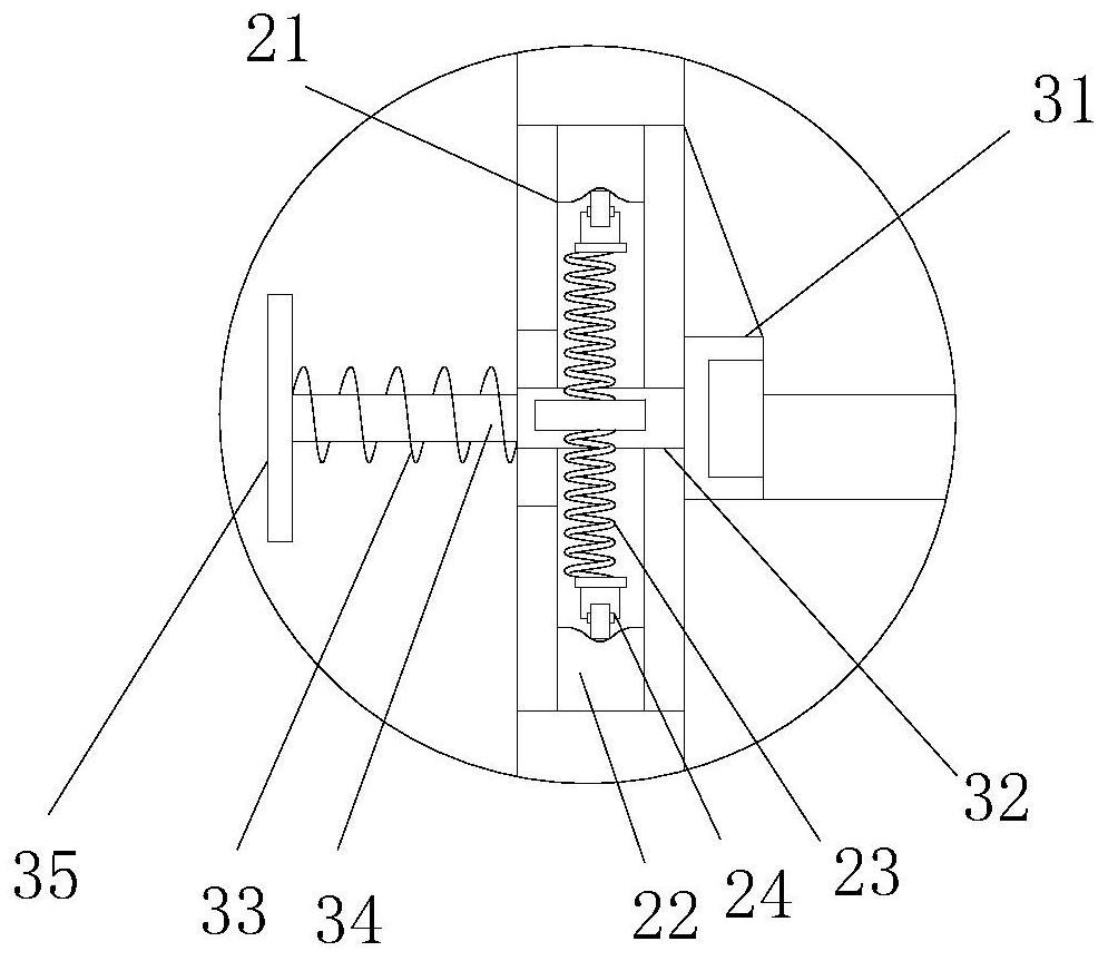
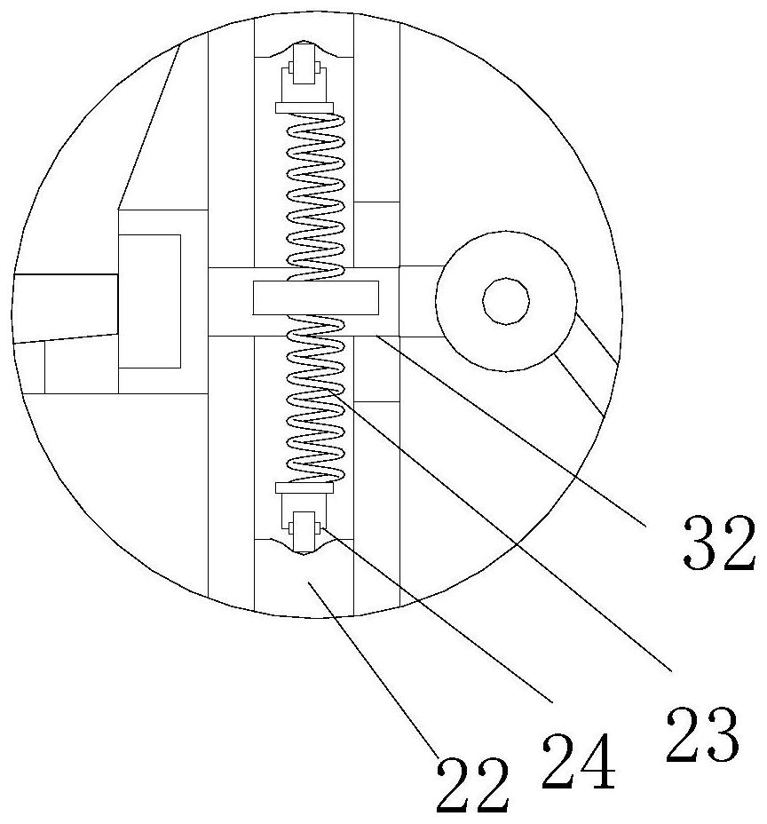
[0028] see figure 1 with figure 2 , the outer ends of the left and right frame 31 are all externally connected to the limit plate 32, the side wall of the operation box 2 is provided with a limit groove 21, and the limit plate 32 is all pierced in the corresponding limit groove 21, The limiting plate 32 on one side is externally connected to the pull rod 36, the base plate 1 is equipped with a work frame 4, the drive plate 41 is installed on the work frame 4, and the pull rod 36 is connected with a drive rod 42 through a movable bolt 43, so One end of the transmission rod 42 is connected to...

Embodiment 2

[0033] see figure 1 ,, this embodiment is further optimized as Embodiment 1. On the basis of it, a support base 11 is installed on the base plate 1, a support frame 12 is installed on the support base 11, and a horizontal frame 12 is installed on the support frame 12. Frame 13, said cross frame 13 is equipped with operating bar 14 by bending bolt, and the bar end of said operating bar 14 is equipped with bending bar 15, and the bottom end of said bending bar 15 is equipped with turning brush 16, and said turning The brush 16 adopts soft brush material, and the material turning motor 17 is installed on the support frame 12, and the driving end of the material turning motor 17 is equipped with a vertical turntable 18, and the outer edge of the vertical turntable 18 is equipped with a connection A bolt 19 , the connection bolt 19 is connected to the working rod 14 through a bent connecting rod 10 .

[0034] After the drying of the water quality on the surface of the tea leaves i...


PUM


Abstract

The invention relates to the field related to tea processing technology, in particular to a high-efficiency tea leaf dehydration device. The device comprises a base plate, an operation box is mountedon the base plate, a dehydration screen board is horizontally mounted in the operation box, outer ends of the dehydration screen board are externally connected with limiting plates respectively, limiting grooves are formed in side walls of the operation box, the limiting plates are arranged in the corresponding limiting grooves respectively in a penetrating manner, the limiting plate on one side is externally connected with a pull rod, an operation frame is mounted on the base plate, a drive plate is mounted on the operation frame, the pull rod is connected with a drive rod through a movable bolt, the other end of the drive rod is connected to the outer edge of the plate surface of the drive plate, the limiting plate on the other side is externally connected with an outer-edge rod, the outer-edge rod is externally connected with a restoring push plate and sleeved with a reset spring, and the reset spring is connected between the restoring push plate and a side wall of the operation boxin a squeezed manner. According to the high-efficiency tea leaf dehydration device, a three-dimensional vibration effect is realized, tea leaves can be further spread, and the dehydration and dryingspeed is enhanced.

Description

technical field [0001] The invention relates to the related field of tea making technology, in particular to a high-efficiency tea dehydration device. Background technique [0002] Cleaned fresh leaves need to be dehydrated. One of the common dehydration methods is to use the sun to evaporate or air-dry the water inside. However, this dehydration method is slow and has been gradually eliminated. Another dehydration method is to use a centrifugal dehydrator. Although the dehydration efficiency is high and the dehydration effect is good, it will lead to the loss of active ingredients in the fresh leaves to varying degrees. [0003] Chinese patent (authorized announcement number: CN206547776U) discloses a high-efficiency tea dehydration device, which controls the left and right cylinders to alternately expand and contract through the controller, so that the arc-shaped filter screen swings back and forth continuously, and cooperates with the vibration of the vibrator to achieve ...

Claims


Application Information

Patent Timeline
Patent Type & Authority Patents(China)
IPC IPC(8): F26B5/00F26B11/00F26B23/00F26B25/04B07B1/04A23F3/06
CPCA23F3/06B07B1/04F26B5/00F26B11/00F26B23/00F26B25/04
Inventor 孟春林
Owner 金寨县蝠牌茶旅有限公司
Learn More