Unmanned aerial vehicle base station group deployment method based on time correlation

A time-dependent, machine-based base station technology, applied in wireless communication, radio transmission system, network planning, etc., can solve problems such as time fluctuation, inability to reflect the communication quality of users, and inability to represent the average network rate, etc., to achieve service capability limited effect

Active Publication Date: 2019-11-08
BEIJING UNIV OF POSTS & TELECOMM
View PDF6 Cites 29 Cited by
  • Summary
  • Abstract
  • Description
  • Claims
  • Application Information

AI Technical Summary

Problems solved by technology

On the other hand, due to the change of non-line-of-sight (NLOS) / line-of-sight (LOS) path energy in the three-dimensional space channel, the occlusion of obstacles is different, and different time Due to the independent multipath fading between slots, the performance at the user site has fluctuations in time; the dynamic construction of the UAV base station group leads to changes in the spatial distribution of sites and link status, which makes the network performance at the user site time-varying ; Since the network performance at the user site fluctuates in time, the instantaneous rate can no longer represent the average network rate, and the instantaneous performance index cannot reflect the actual communication quality at the user site. The deployment of UAV base stations cannot achieve the optimal deployment of UAV base stations. It is necessary to consider the impact of large-scale time network performance based on time correlation on the deployment of UAV base stations.

Method used


Image

  • Unmanned aerial vehicle base station group deployment method based on time correlation
  • Unmanned aerial vehicle base station group deployment method based on time correlation
  • Unmanned aerial vehicle base station group deployment method based on time correlation

Examples


Embodiment Construction

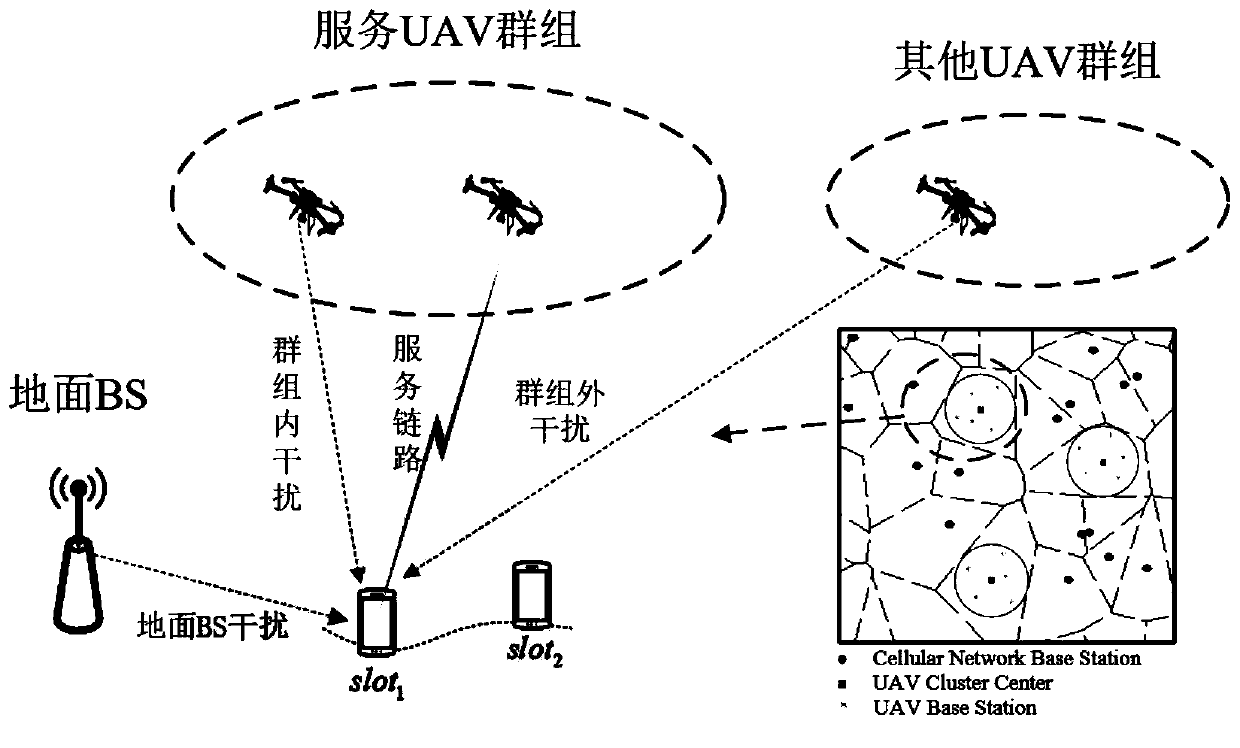
[0044] Aiming at the coverage blind area of ​​the ground base station, the present invention proposes a deployment method for UAV base station groups to fill in the blind area. The network model is shown in the attached figure 1 shown. attached figure 1 The subgraph in the figure shows the network topology when the UAV base station group fills in the blind area: there are multiple ground base station coverage blind areas (ie, target areas), and multiple UAV base station groups will cover these target areas. Provide services to users; deploy UAV base station groups in a circular area according to the location and range of the target area, each group contains multiple UAV base stations; the center of the circular area corresponds to the regional center of the target area , the radius of the circular area is determined by the size of the target area; the deployment height of the drone is related to the average height of the buildings in the target area. Such as figure 1 As sho...


PUM


Abstract

The invention provides an unmanned aerial vehicle base station group deployment method based on time correlation. According to the method, a coverage blind area of a ground base station serves as a target area covered by an unmanned aerial vehicle base station group, and the deployment position and the deployment range of the unmanned aerial vehicle base station group are determined according to environmental parameters (position, size and building average height) of the target area. Because link condition fluctuation is caused by conversion between a sight distance link and a non-sight distance link in a three-dimensional space channel and change of shielding conditions of obstacles during transmission of an unmanned aerial vehicle base station, the instantaneous rate does not accuratelyrepresent the average rate of a network any more, time correlation is introduced, and network performance of large-scale time is obtained. Specifically, the interference correlation coefficient is used for measuring the time correlation, the joint coverage rate is used for representing the network performance of large-scale time, and the optimal deployment height and the number of unmanned aerialvehicle base stations are determined according to the change relation of the joint coverage rate along with the deployment height of the unmanned aerial vehicle base station group and the number of the unmanned aerial vehicle base stations in the group.

Description

technical field [0001] The present invention relates to the technical field of wireless communication, and in particular to the deployment design of a UAV base station group based on time correlation in a UAV (Unmanned aerial vehicle, UAV for short) base station network. Background technique [0002] With significant advancements in UAV (Unmanned aerial vehicle, UAV) technology, such as better power management techniques, increased payload capacity, longer average flight time, etc., UAVs can be used for a variety of purposes, such as Shooting, surveillance, transportation, communication, etc., drones become a flexible solution to enhance the capabilities of current cellular networks. In terms of communication, due to the high dynamic characteristics of drones and the line-of-sight transmission link between drones and ground users, drones can be used as temporary base stations for hotspot areas with large data traffic requirements (such as large-scale activities, Concerts, s...

Claims


Application Information

Patent Timeline
Patent Type & Authority Applications(China)
IPC IPC(8): H04W16/18H04W24/08H04W24/02H04B7/185H04W88/08H04L12/24
CPCH04B7/18504H04B7/18506H04L41/145H04W16/18H04W24/02H04W24/08H04W88/08
Inventor 张鸿涛杨丽云郜崇黄婉晴
Owner BEIJING UNIV OF POSTS & TELECOMM
Why Eureka
Try Eureka