
Coal screening device and using method thereof

A screening device and coal technology, applied in chemical instruments and methods, sieves, solid separation, etc., can solve the problems of easy clogging of sieve holes, wear of hammer heads, and large maintenance, so as to improve screening efficiency and increase coal production. The effect of low circulation and manufacturing cost

Pending Publication Date: 2019-11-12
陕西未来能源化工有限公司
View PDF0 Cites 2 Cited by
  • Summary
  • Abstract
  • Description
  • Claims
  • Application Information

AI Technical Summary

Problems solved by technology

[0002] At present, the coal screening systems of thermal power plants, coal preparation plants and coal chemical enterprises mostly use screening equipment such as vibrating screens, drum screens, roller screens, and sinusoidal screens. These screening equipments are noisy and easy to block the screen holes. , high energy consumption, large maintenance and other disadvantages
Especially when the water content of the coal is slightly high, the screening efficiency of the above-mentioned screening equipment will be low, so that a large amount of crushed coal will enter the crusher, causing the gap of the grate to control the particle size inside the crusher to be blocked, and the wear of the hammer head will be accelerated exponentially. As a result, the vibration efficiency of the inner rotor of the crusher is reduced, the cost of spare parts and maintenance workload are increased, and the effective and safe operation time of the crusher is reduced. In severe cases, shutdown accidents occur, which cannot meet the production requirements of enterprises

Method used


Image

  • Coal screening device and using method thereof
  • Coal screening device and using method thereof
  • Coal screening device and using method thereof

Examples


Embodiment 1

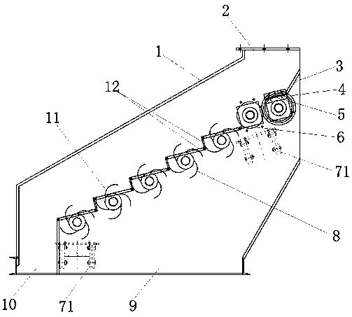
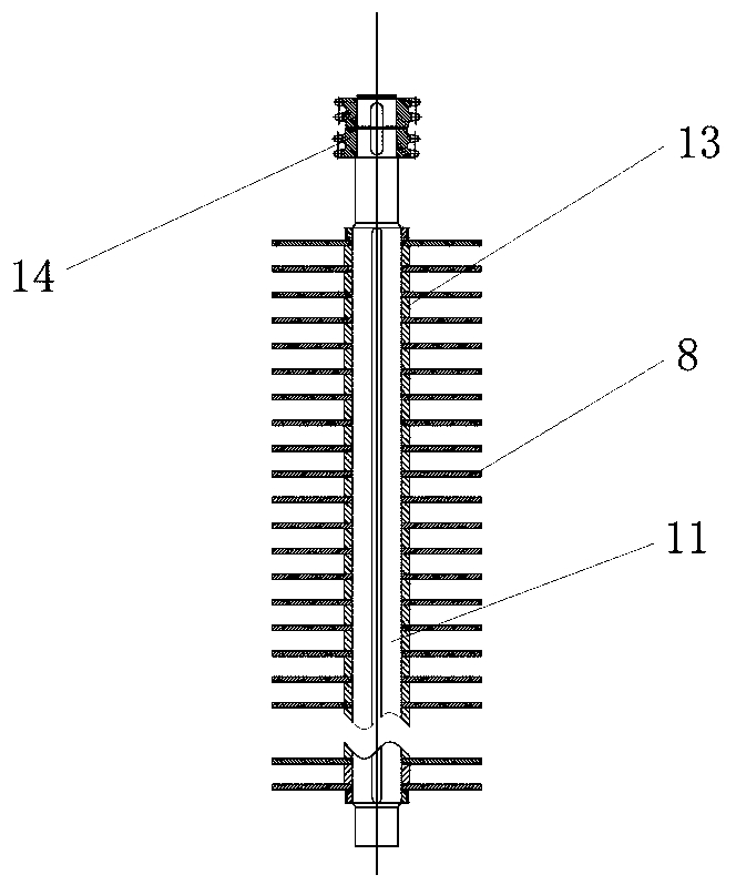
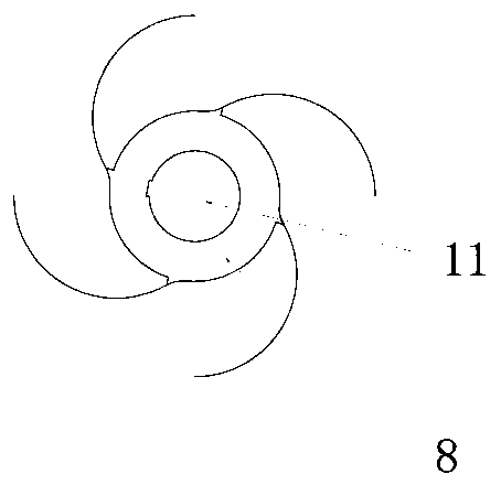
[0025] Such as figure 1 , 2 , 3, and 4, the coal screening device of the present invention comprises a housing 1, one side of the top of the housing is provided with a feed inlet 2, and the bottom is provided with small and large particle discharge ports 9,10; the housing 1 There is a stepped sieve plate 12 extending obliquely from the side of the feed port 2 to the direction of the large particle discharge port 10. The stepped sieve plate 12 passes through a plurality of sieve bars and spliced ​​longitudinally to form a sieve plate. The stepped planes are combined and connected to form an inclined ladder; the lower side of the feed port 2 is provided with a baffle 3 for guiding, and the baffle 3 extends to the first-stage feed buffer rotary screen roller 4 and the second-stage feed buffer rotary screen. On the upper side of the sieve roller 6, the uppermost end of the stepped sieve plate 12 is connected to the lower side of the secondary feed buffer rotary sieve roller 6, wh...

Embodiment 2

[0034] The inventive device of the present embodiment comprises a housing 1, one side of the top of the housing 1 is provided with a feed inlet 2, and the bottom is provided with small and large particle discharge outlets 9, 10; 2 The stepped sieve plate 12 extending obliquely towards the large particle discharge port 10; the stepped sieve plate 12 is spliced ​​longitudinally by a plurality of sieve bars side by side to form a sieve plate, and is connected by a combination of a stepped facade and a stepped plane to form an inclined ladder shape; the lower side of the feed port 2 is provided with a baffle 3 for guiding, and the baffle 3 extends to the upper side of the first-level feed buffer rotary sieve roller 4 and the second-stage feed buffer rotary sieve roller 6, and the steps The uppermost end of the shaped sieve plate 12 is connected to the lower side of the secondary feed buffer rotary screen roller 6, and is used to receive the coal that is buffered and pushed down fro...

Embodiment 3

[0039] The inventive device of the present embodiment comprises a housing 1, one side of the top of the housing 1 is provided with a feed inlet 2, and the bottom is provided with small and large particle discharge outlets 9, 10; 2 The stepped sieve plate 12 extending obliquely towards the large particle discharge port 10; the stepped sieve plate 12 is spliced ​​longitudinally by a plurality of sieve bars side by side to form a sieve plate, and is connected by a combination of a stepped facade and a stepped plane to form an inclined ladder shape; the lower side of the feed port 2 is provided with a baffle 3 for guiding, and the baffle 3 extends to the upper side of the first-level feed buffer rotary sieve roller 4 and the second-stage feed buffer rotary sieve roller 6, and the steps The uppermost end of the shaped sieve plate 12 is connected to the lower side of the secondary feed buffer rotary screen roller 6, and is used to receive the coal that is buffered and pushed down fro...


PUM

PropertyMeasurementUnit
Thicknessaaaaaaaaaa
Thicknessaaaaaaaaaa
Thicknessaaaaaaaaaa

Abstract

The invention discloses a coal screening device and a using method thereof. The coal screening device comprises a shell, a baffle plate, a first-stage feeding buffer rotating carrier roller, a second-stage feeding buffer rotating carrier roller, a rotating shafts, rotating wheels with gear teeth, stepped screen plates and a speed reducing driving mechanism, wherein a feeding hole is formed in oneside of the top of the shell, and a large-particle discharging hole and a small-particle discharging hole are formed in the bottom of the shell; the baffle plate is arranged on the position, below thefeeding hole, of the interior of the shell; and the first-stage feeding buffer rotating carrier roller, the second-stage feeding buffer rotating carrier roller and the plurality of rotating shafts are obliquely arranged on the two inner walls of the shell from top to bottom in sequence, and the plurality of rotating wheels with the gear teeth and corresponding stepped screen plates are arranged on each rotating shaft in parallel. When the coal is screened, the noise is low, the blockage is not easy, the energy consumption is low, the maintenance is basically not needed, and a subsequent crusher is not easy to block in the process of screening the sticky coal containing certain moisture.

Description

technical field [0001] The invention relates to the field of coal, in particular to a coal screening device and a method for using the same. Background technique [0002] At present, the coal screening systems of thermal power plants, coal preparation plants and coal chemical enterprises mostly use screening equipment such as vibrating screens, drum screens, roller screens, and sinusoidal screens. These screening equipments are noisy and easy to block the screen holes. , high energy consumption, large maintenance and other shortcomings. Especially when the water content of the coal is slightly high, the screening efficiency of the above-mentioned screening equipment will be low, so that a large amount of crushed coal will enter the crusher, causing the gap of the grate to control the particle size inside the crusher to be blocked, and the wear of the hammer head will be accelerated exponentially. As a result, the vibration efficiency of the inner rotor of the crusher is red...

Claims


Application Information

Patent Timeline
IPC IPC(8): B02C23/14B07B9/00B07B1/50B07B1/46
CPCB02C23/14B07B9/00B07B1/50B07B1/46
Inventor 唐广文王言成冯质杭刘勇
Owner 陕西未来能源化工有限公司
Features
  • Generate Ideas
  • Intellectual Property
  • Life Sciences
  • Materials
  • Tech Scout
  • Unparalleled Data Quality
  • Higher Quality Content
  • 60% Fewer Hallucinations
Learn More