Cooling cover used before spinning of hub

A cooling cover and hub technology, applied in metal processing equipment, forming tools, manufacturing tools, etc., can solve problems such as deformation of supporting parts, easy deformation of hubs, and processing failure, so as to avoid obstacles, be easy to operate, and reduce occupied space Effect

Pending Publication Date: 2019-11-12
KANGXIANG ALUMINUM IND TAIZHOU CO LTD
View PDF0 Cites 0 Cited by
  • Summary
  • Abstract
  • Description
  • Claims
  • Application Information

AI Technical Summary

Problems solved by technology

[0003] During the processing of the existing wheel hub, the wheel hub needs to be heated to facilitate the die-casting on the edge of the wheel hub later, but during the heating of the wheel hub, the entire wheel hub is in a state of deformation, which leads to the die-casting of the edge of the wheel hub. The support parts at the position will also be deformed, resulting in processing failure. The current common cooling method is to place the entire wheel hub in water for cooling, but it is inconvenient during later spinning. Therefore, the present invention provides a cooling cover before wheel hub spinning

Method used


Image

  • Cooling cover used before spinning of hub
  • Cooling cover used before spinning of hub
  • Cooling cover used before spinning of hub

Examples


Embodiment 1

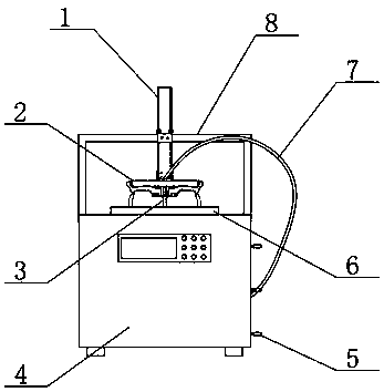
[0022] see figure 1 and figure 2 , the present invention provides a technical solution: a cooling cover before hub spinning, including a body 4, the top of the body 4 is provided with a bracket 8 in a C-shaped structure, and the two ends of the bracket 8 are fixed on the top edge of the slide rail 1 , the middle position of the surface of the support 8 is fixed with a slide rail 1, the surface of the slide rail 1 is provided with a clamping part that can slide up and down, the surface of the clamping part is fixed with a water outlet tray 2, the water outlet tray 2 is a cylindrical structure, and the water outlet The bottom surface of the disc 2 is uniformly provided with a plurality of water outlet holes, the diameter of the water outlet disc 2 is three-quarters of the diameter of the hub to be processed, and a cooling water tank is placed at the inner bottom of the body 4, and the connection between the water outlet disc 2 and the cooling water tank There are cooling water...

Embodiment 2

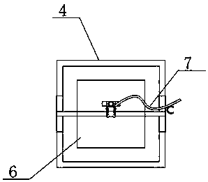
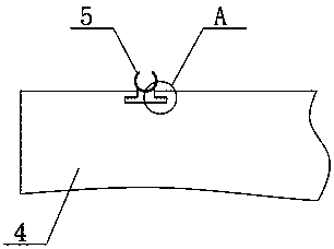
[0024] see Figure 1-Figure 4 , the present invention provides a technical solution: a cooling cover before hub spinning, including a body 4, the top of the body 4 is provided with a bracket 8 in a C-shaped structure, and the two ends of the bracket 8 are fixed on the top edge of the slide rail 1 , the middle position of the surface of the support 8 is fixed with a slide rail 1, the surface of the slide rail 1 is provided with a clamping part that can slide up and down, the surface of the clamping part is fixed with a water outlet tray 2, the water outlet tray 2 is a cylindrical structure, and the water outlet The bottom surface of the disc 2 is uniformly provided with a plurality of water outlet holes, the diameter of the water outlet disc 2 is three-quarters of the diameter of the hub to be processed, and a cooling water tank is placed at the inner bottom of the body 4, and the connection between the water outlet disc 2 and the cooling water tank There are cooling water pipe...


PUM


Abstract

The invention discloses a cooling cover used before spinning of a hub. The cooling cover comprises a machine body; a support which is of a C-shaped structure is disposed at the top of the machine body; the two ends of the support are fixed to the edge of the top end of a sliding rail; the sliding rail is fixed to the middle of the surface of the support; a clamping part which can slide up and downis disposed on the surface of the sliding rail; a water outflowing disc is fixed to the surface of the clamping part; a cooling water tank is placed at the bottom end of the interior of the machine body; and a cooling water pipe is connected between the water outflowing disc and the cooling water tank. By means of the water outflowing disc, during machining of the hub, only the middle of the hubcan be cooled, the portion, which needs spinning, of the edge of the hub is not cooled, thus later-stage machining is guaranteed, the mode is simpler than an existing cooling mode of directly placingin water, meanwhile the phenomenon of high spinning difficulty does not occur, and the phenomenon of deformation of the middle of the hub is avoided.

Description

technical field [0001] The invention belongs to the technical field of hub processing equipment, and in particular relates to a cooling cover before hub spinning. Background technique [0002] The wheel hub is a barrel-shaped metal part whose center is mounted on the shaft, and is also called a rim, a steel ring, a wheel, and a tire bell. There are many types of hubs according to diameter, width, molding method and material. In the production of hubs, more parts and equipment are needed, and cooling equipment is one of the accessories in hub processing. [0003] During the processing of the existing wheel hub, the wheel hub needs to be heated to facilitate the die-casting on the edge of the wheel hub later, but during the heating of the wheel hub, the entire wheel hub is in a state of easy deformation, resulting in that when the edge of the wheel hub is die-cast, the middle of the hub The supporting part at the position will also be deformed, resulting in processing failure...

Claims


Application Information

Patent Timeline
Patent Type & Authority Applications(China)
IPC IPC(8): B21D37/16B21D22/14B21D53/26
CPCB21D22/14B21D37/16B21D53/26
Inventor 张博钧
Owner KANGXIANG ALUMINUM IND TAIZHOU CO LTD
Why Eureka
Try Eureka