An interlocking aluminum alloy air storage cylinder assembly and manufacturing method thereof

A production method and the technology of the air storage tank, which are applied in the direction of the hydraulic brake transmission device, etc., can solve the problems of poor installation effect, achieve the effects of convenient operation, light weight effect, and low installation difficulty

Active Publication Date: 2020-10-09
DONGFENG COMML VEHICLE CO LTD
View PDF4 Cites 0 Cited by
  • Summary
  • Abstract
  • Description
  • Claims
  • Application Information

AI Technical Summary

Problems solved by technology

[0006] The purpose of the present invention is to overcome the defects and problems of poor installation effect in the prior art, and provide an interlocking aluminum alloy air storage cylinder assembly with better installation effect and its manufacturing method

Method used


Image

  • An interlocking aluminum alloy air storage cylinder assembly and manufacturing method thereof
  • An interlocking aluminum alloy air storage cylinder assembly and manufacturing method thereof
  • An interlocking aluminum alloy air storage cylinder assembly and manufacturing method thereof

Examples


Embodiment 1

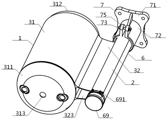
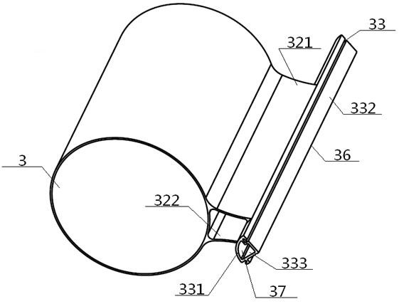
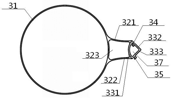
[0066] see Figure 1 to Figure 13, an interlocking aluminum alloy gas storage cylinder assembly, including a cylinder unit 1 and a fixing device 2 connected to each other, the cylinder unit 1 includes a No. 1 gas storage cylinder 3; the fixing device 2 includes a support rod 6, and the support rod The inside of 6 is provided with intersecting pole A inner cutting surface 61 and pole second inner cutting surface 62, and the pole first inner cutting surface 61 is connected with a pole first lock convex strip 611, and the pole second inner cutting surface 62 is provided with a pole second lock groove 621; The No. 1 gas tank 3 includes a No. 1 cylinder body 31, a No. 1 connecting portion 32 and a No. 1 interlocking portion 33, and the No. 1 interlocking portion 33 includes a No. 1 inner connecting plate 331, a No. 1 upper sloping plate 332 and a No. There is a No. 1 lock groove 34 on the No. 1 upper slant plate 333 and the No. 1 upper slant plate 332. A No. 1 lock protrusion 35 is...

Embodiment 2

[0069] Basic content is the same as embodiment 1, the difference is:

[0070] The cylinder unit 1 also includes a No. 2 air storage tank 4 having the same structure as the No. 1 gas storage tank 3. The No. 2 gas storage tank 4 includes a No. 2 cylinder body 41, a No. 2 inner connecting plate 431, a No. Lower inclined plate 433, No. 2 lock groove 44 and No. 2 lock convex strip 45; the inner cut surface 61 of the rod first and the inner cut surface 62 of the rod second are located on the first inclined plane 66, and the outer end of the first cut surface 61 of the rod is connected with Rod A lock convex strip 611, the inner end of the rod A inner cut surface 61 is connected with the inner end of the rod B inner cut surface 62, and the outer end of the rod B inner cut surface 62 is provided with a rod B lock groove 621, and the rod A lock convex The bar 611 is interlocked with the No. 1 lock groove 34, the No. 1 lock convex strip 35 is interlocked with the No. 2 lock groove 44, a...

Embodiment 3

[0072] Basic content is the same as embodiment 1, the difference is:

[0073] The cylinder unit 1 also includes a No. 2 air storage tank 4 having the same structure as the No. 1 gas storage tank 3. The No. 2 gas storage tank 4 includes a No. 2 cylinder body 41, a No. 2 inner connecting plate 431, a No. The lower inclined plate 433, No. 2 lock groove 44 and No. 2 lock protrusion 45; the inside of the support rod 6 is also provided with a rod C inner cut surface 63 and a rod D inner cut surface 64, and the outside of the rod C inner cut surface 63 The end is connected with a rod C lock convex strip 631, the inner end of the rod C inner cut surface 63 is connected with the inner end of the rod A inner cut surface 61, and the outer end of the rod A inner cut surface 61 is connected with a rod A lock convex strip 611, the rod The outer end of the inner cutting surface 64 of the third rod is provided with a lock groove 641 of the third rod. Groove 621, the No. 2 inclined plane 67 t...


PUM


Abstract

An interlocking type aluminum alloy air storage cylinder assembly comprises a cylinder unit and a fixing device. A rod A locking convex strip and a rod B locking groove are arranged in a supporting rod in the fixing device, the cylinder unit at least comprises an air storage cylinder, the first air storage cylinder comprises a first cylinder body, a first connecting part and a first interlocking part, the first interlocking part comprises a first inner connecting plate, a first upper inclined plate and a first lower inclined plate, the first upper inclined plate is provided with a first locking groove, the first lower inclined plate is connected with a first locking convex strip, one end of the first connecting part is connected with the side wall of the first cylinder body, the other endof the first connecting part is connected with the inner side surfaces of the upper end and the lower end of the first inner connecting plate, the outer side surface of the upper end of the first inner connecting plate is connected with the higher end of the first upper inclined plate, and the outer side surface of the lower end of the first inner connecting plate is connected with the lower end of the first lower inclined plate. Any single locking groove is in interlocking connection fit with any single locking convex strip. By means of the design, the installation effect is good, and the light weight effect is good.

Description

technical field [0001] The invention relates to an air storage cylinder assembly, which belongs to the technical field of automobile brake systems, in particular to an interlocking aluminum alloy air storage cylinder assembly and a manufacturing method thereof, which are particularly suitable for improving the installation effect. Background technique [0002] At present, most commercial vehicles use steel air storage cylinder assemblies, which not only results in a large weight of the air storage cylinder assembly, but also does not meet the needs of high-end commercial vehicles. The lightweight design is easy to increase fuel consumption, and it is not conducive to the installation of the air storage cylinder assembly. The installation difficulty is increased, and the installation cost is increased. [0003] The invention patent with the publication number CN103693031A and the publication date of April 2, 2014 discloses an aluminum-magnesium alloy gas storage tank and its ...

Claims


Application Information

Patent Timeline
Patent Type & Authority Patents(China)
IPC IPC(8): B60T11/26B23P15/00
CPCB23P15/00B60T11/26
Inventor 杨小见郝守海宁忠翼田静
Owner DONGFENG COMML VEHICLE CO LTD
Why Eureka
Try Eureka