

Composite trolley of improved structure
An improved sub-trolley technology, which is applied to trolleys, motor vehicles, multi-axis trolleys, etc., can solve the difficult installation and separation of sub-trolleys and parent trolleys, limit the speed of goods, and increase the labor of workshop staff. Strength and other issues
- Summary
- Abstract
- Description
- Claims
- Application Information
AI Technical Summary
Problems solved by technology
Method used
Image

Examples
specific Embodiment example 1
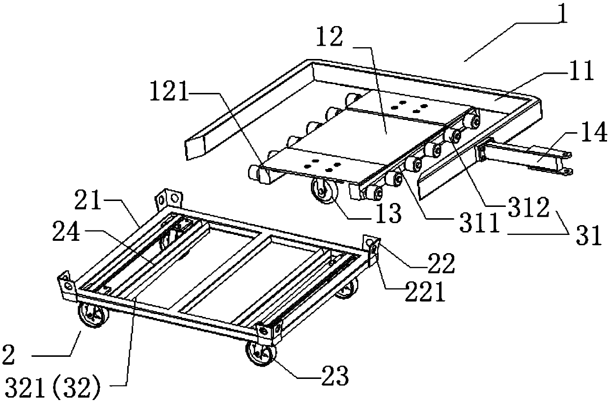
[0022] A structure-improved sub-mother trolley, comprising: a mother trolley 1, a sub-trolley 2, the mother trolley 1 includes a U-shaped mother frame 11, and is connected with a screw on the inner side of the middle vertical plate surface of the U-shaped mother frame 11 or Welded and fixed mother trolley load plate 12, two rollers 13 installed on the two ends of the mother trolley load plate 12 near the two ends of the length and located on the bottom surface of the mother trolley load plate 12, perpendicular to the front side plate surface of the U-shaped mother frame 11 The screwed drawbar 14, the two sides of the width of the carrier plate 12 of the mother car are respectively screwed or welded with reinforcement plates 121; Four rollers 23 on the bottom end surface, four bent corner plates 22 screwed on the four corners of the rectangular mother frame 21 and located on the upper end surface of the rectangular mother frame 21, and two support plates 24 transversely welded o...
specific Embodiment example 2
[0032] A structure-improved sub-mother trolley, comprising: a mother trolley 1, a sub-trolley 2, the mother trolley 1 includes a U-shaped mother frame 11, and is connected with a screw on the inner side of the middle vertical plate surface of the U-shaped mother frame 11 or Welded and fixed mother trolley load plate 12, two rollers 13 installed on the two ends of the mother trolley load plate 12 near the two ends of the length and located on the bottom surface of the mother trolley load plate 12, perpendicular to the front side plate surface of the U-shaped mother frame 11 The screwed drawbar 14, the two sides of the width of the carrier plate 12 of the mother car are respectively screwed or welded with reinforcement plates 121; Four rollers 23 on the bottom end surface, four bent corner plates 22 screwed on the four corners of the rectangular mother frame 21 and located on the upper end surface of the rectangular mother frame 21, and two support plates 24 transversely welded o...
specific Embodiment example 3
[0042] A structure-improved sub-mother trolley, comprising: a mother trolley 1, a sub-trolley 2, the mother trolley 1 includes a U-shaped mother frame 11, and is connected with a screw on the inner side of the middle vertical plate surface of the U-shaped mother frame 11 or Welded and fixed mother trolley load plate 12, two rollers 13 installed on the two ends of the mother trolley load plate 12 near the two ends of the length and located on the bottom surface of the mother trolley load plate 12, perpendicular to the front side plate surface of the U-shaped mother frame 11 The screwed drawbar 14, the two sides of the width of the carrier plate 12 of the mother car are respectively screwed or welded with reinforcement plates 121; Four rollers 23 on the bottom end surface, four bent corner plates 22 screwed on the four corners of the rectangular mother frame 21 and located on the upper end surface of the rectangular mother frame 21, and two support plates 24 transversely welded o...
PUM
 Abstract
Description
Claims
Application Information