Sewage lifting system
A technology for sewage lifting and sewage, which is applied in the direction of waterway systems, water supply devices, drainage structures, etc., can solve the problems of sewage lifting difficult to adapt to complex terrain, poor sewage lifting effect, etc., to facilitate popularization and application, reduce layout difficulty, and save manufacturing and maintenance cost effects
- Summary
- Abstract
- Description
- Claims
- Application Information
AI Technical Summary
Problems solved by technology
Method used
Image

Examples
Embodiment 1
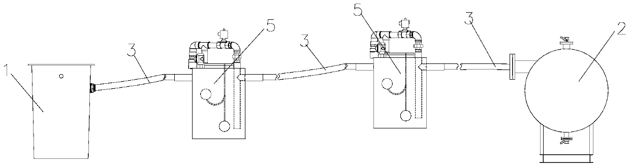
[0023] Embodiment 1: as figure 1 , figure 2 As shown, a sewage lifting system is used for the layout of rural sewage pipe networks, including a group of collection wells 1 connected to the atmosphere, which are distributed near each household to collect sewage from each household. A vacuum collection tank 2 is also provided, and a vacuum pump is used to generate negative pressure for collecting sewage from each collection well 1, and a vacuum delivery pipeline 3 connecting the collection well and the vacuum collection tank 2 is provided between the collection well 1 and the vacuum collection tank 2 .
[0024] When the height difference between the collection well 1 and the vacuum collection tank 2 is less than the height that the vacuum collection tank 2 can lift, the sewage in the collection well 1 can be smoothly transported to the vacuum collection tank 2 through the vacuum delivery pipeline 3 . When the height difference between the collection well 1 and the vacuum col...
Embodiment 2
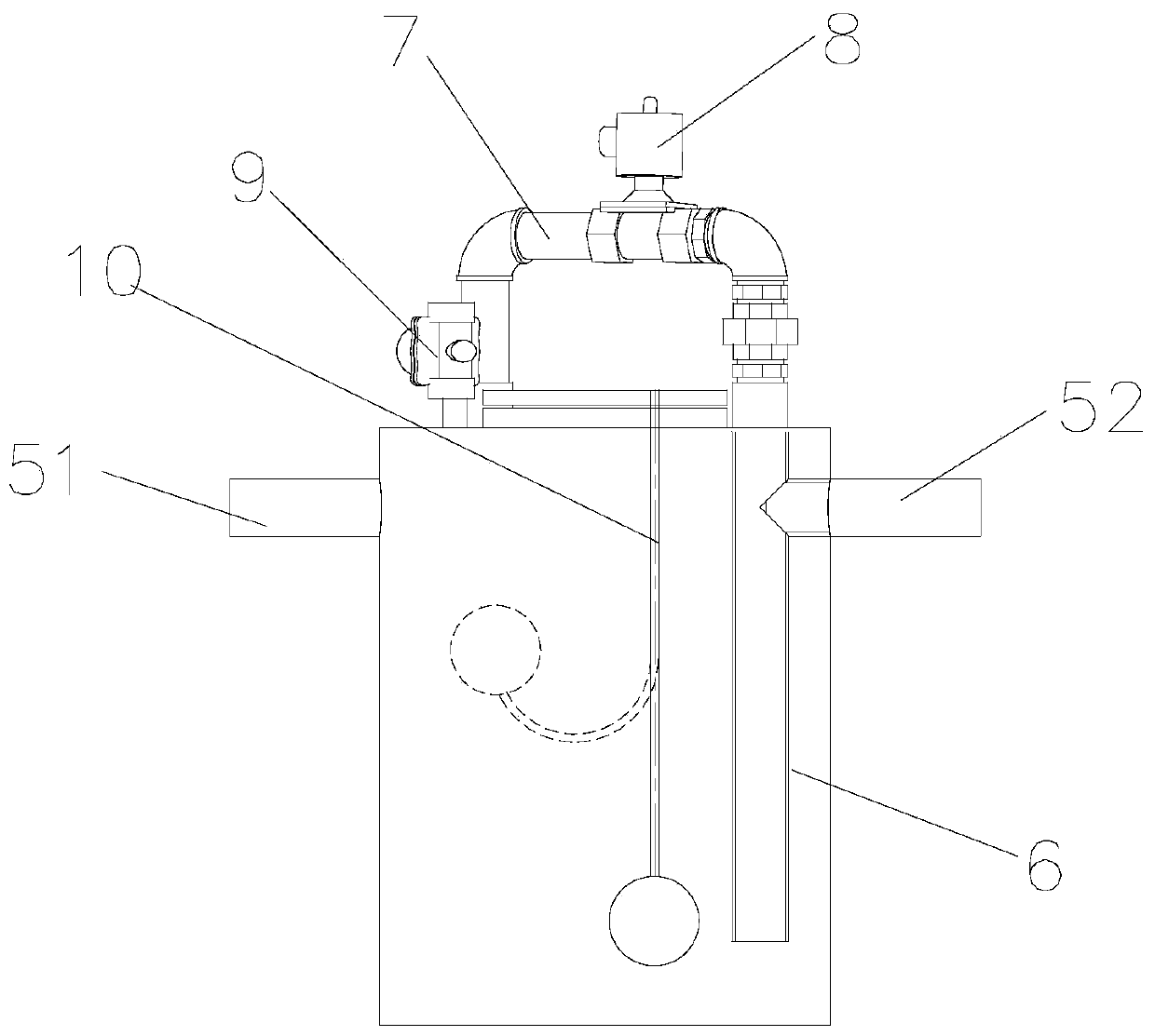
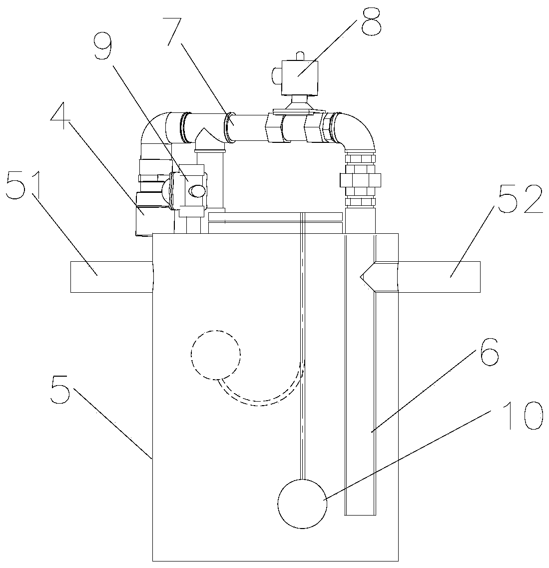
[0027] like figure 1 , Figures 3 to 6As shown, a sewage lifting system is used for the layout of rural sewage pipe networks, including a group of collection wells 1 connected to the atmosphere, which are distributed near each household to collect sewage from each household. A vacuum collection tank 2 is also provided, and a negative pressure is generated by a vacuum pump to collect sewage from each collection well 1, and a vacuum conveying pipe connecting the collection well 1 and the vacuum collection tank 2 is arranged between the collection well 1 and the vacuum collection tank 2 Road 3. A group of lift shafts 5 are arranged in series on the vacuum conveying pipeline 3, and a bypass pipe 7 is arranged above the lift shaft 5. One end of the bypass pipe 7 communicates with the top of the lift shaft 5, and the other end communicates with the drain pipe. The top of 6 is connected; the bypass pipe 7 is provided with a bypass valve 8, and the top of the lifting shaft 5 is also...
PUM
 Abstract
Description
Claims
Application Information