
Hydraulic bolt mechanism

A hydraulic and latching technology, applied in the direction of fluid pressure actuating devices, etc., can solve the problems of inaccurate positioning, difficult structural arrangement, inability to observe the action of the locking mechanism, etc., to meet the requirements of repeated positioning accuracy, high repeated positioning accuracy, easy to use The effect of observation and maintenance

Active Publication Date: 2019-11-12
北京安泰隆机电技术有限公司
View PDF8 Cites 0 Cited by
  • Summary
  • Abstract
  • Description
  • Claims
  • Application Information

AI Technical Summary

Problems solved by technology

At present, there are the following automatic locking forms at home and abroad: the first one is an automatic locking mechanism that uses a hydraulic cylinder to directly drive the plug-in pin. Difficult to carry out structural arrangement, and the insertion force is greater than the extraction force, which is prone to the problems of poor extraction and sticking; the second is the locking form of the self-locking cylinder, that is, the locking mechanism is designed inside the cylinder. When the cylinder is extended or retracted to When the stroke is full, the oil cylinder is locked into a rigid rod by the internal locking mechanism. This kind of locking mechanism has a high manufacturing cost for the self-locking oil cylinder. There is no sensor feedback signal for whether the locking and unlocking are in place, and the failure cannot be self-checked, and the oil cylinder cannot be observed manually. The internal locking mechanism operates, and it is difficult to maintain after a failure; the third is to install a hydraulic lock outside the hydraulic cylinder, and lock or unlock the hydraulic cylinder through the action of hydraulically controlling the lock to hold or loosen. The locking mechanism has high manufacturing cost, cannot be positioned accurately, cannot meet the requirements of high repeat positioning accuracy, and has a short service life

Method used


Image

  • Hydraulic bolt mechanism
  • Hydraulic bolt mechanism
  • Hydraulic bolt mechanism

Examples


Embodiment Construction

[0029] In order to make the purpose, technical solutions and advantages of the embodiments of the present invention clearer, the technical solutions in the embodiments of the present invention will be clearly and completely described below in conjunction with the drawings in the embodiments of the present invention. Obviously, the described embodiments It is a part of embodiments of the present invention, but not all embodiments. Based on the embodiments of the present invention, all other embodiments obtained by persons of ordinary skill in the art without making creative efforts belong to the protection scope of the present invention.

[0030] Below in conjunction with embodiment the invention is described in further detail.

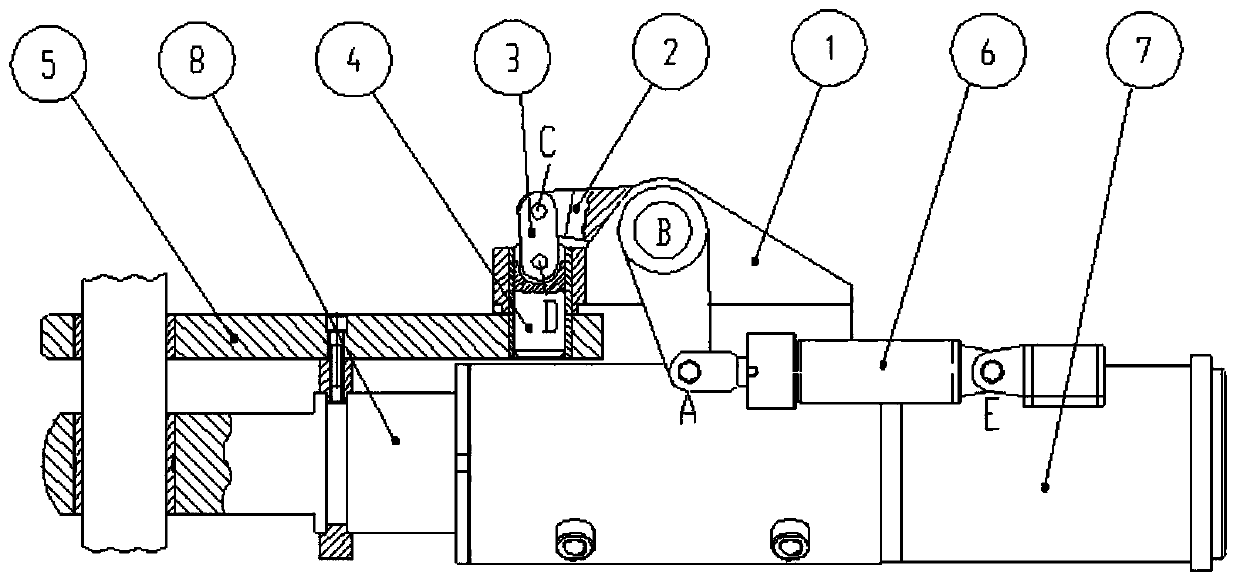
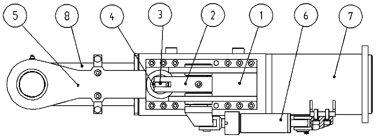
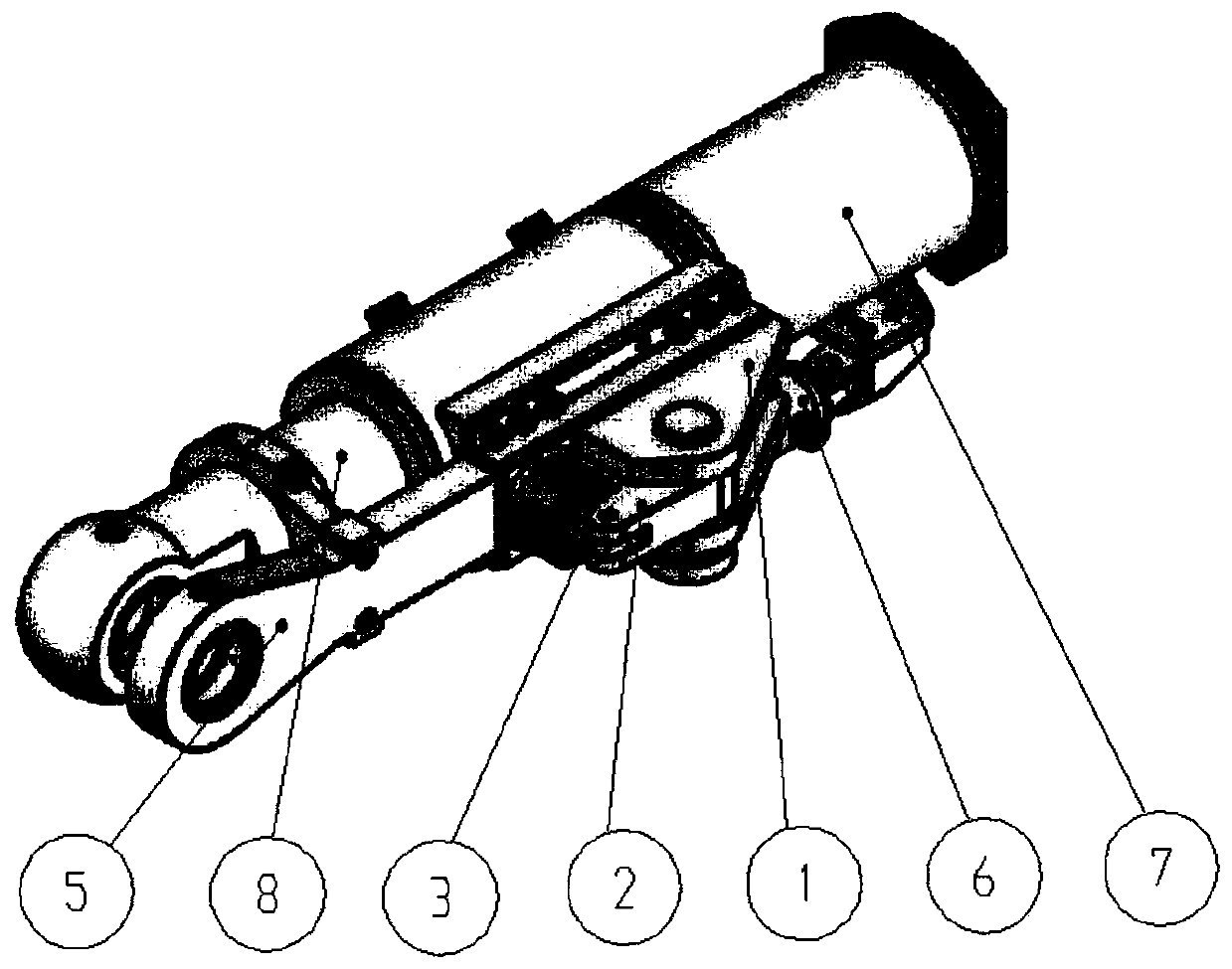
[0031] The invention provides a hydraulic latch mechanism, such as Figure 1 to Figure 3 As shown, comprising: a horizontally arranged hydraulic cylinder and a bolt assembly located on one side of the hydraulic cylinder;

[0032] The hydraulic cylind...


PUM


Abstract

The invention relates to a hydraulic bolt mechanism. The hydraulic bolt mechanism comprises a horizontally arranged hydraulic oil cylinder and a bolt assembly arranged at one side of the hydraulic oilcylinder. The hydraulic oil cylinder comprises a cylinder barrel and a cylinder rod coaxial with the cylinder barrel. The bolt assembly comprises a crank slider structure and a telescopic structure.The hydraulic bolt mechanism is mainly used for mechanical locking of the hydraulic oil cylinder, the hydraulic bolt mechanism is attached to the outside of the hydraulic oil cylinder, so that the manual observation and maintenance operation are easy; and the locking mode with shafts and holes matched is adopted, so that the repeated positioning precision is high.

Description

technical field [0001] The invention relates to the field of engineering machinery, in particular to a hydraulic latch mechanism. Background technique [0002] With the vigorous development of national defense technology in our country, higher requirements are put forward for the repeated positioning accuracy of the lifting mechanism of communication, radar and other electronic equipment in the unfolded state. In order to ensure the required tactical indicators in actual combat, and at the same time It has the maneuverability of rapid erection or withdrawal, so the radar lifting mechanism is required to automatically lift the electronic equipment to a certain height and pitch angle, and automatically lock the radar lifting mechanism as a rigid body after the lifting is in place. At present, there are the following automatic locking forms at home and abroad: the first one is an automatic locking mechanism that uses a hydraulic cylinder to directly drive the plug-in pin. Diff...

Claims


Application Information

Patent Timeline
Patent Type & Authority Applications(China)
IPC IPC(8): F15B15/26F15B15/28C22C38/04C22C38/02C22C38/44C22C38/22
CPCF15B15/261F15B15/2807C22C38/04C22C38/02C22C38/44C22C38/22
Inventor 李瑞功
Owner 北京安泰隆机电技术有限公司
Learn More