Anti-crushing flange bolt
A technology for crushing flange surfaces and bolts, which is applied in the field of fasteners and can solve problems such as crushing and easy scratches
- Summary
- Abstract
- Description
- Claims
- Application Information
AI Technical Summary
Problems solved by technology
Method used
Image

Examples
Embodiment 1
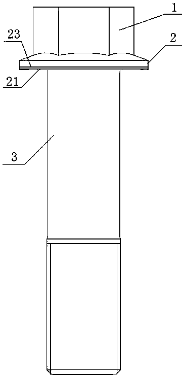
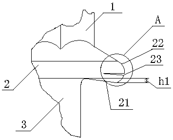
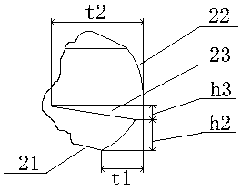
[0042] see figure 1 with figure 2 , an anti-collapse flange bolt, comprising a bolt head 1, a bolt shank 3, and a flange 2 connected between the screw head 1 and the bolt shank 3, the flange 2 The side facing the bolt shank 3 is the flange bottom surface 21, the flange bottom surface 21 is an inner concave surface, and the flange bottom surface 21 protrudes downward near the flange cylindrical surface 22. The bottom surface of the flange 21 is a line segment inclined downward in the axial section, and the downward inclination angle is 1°. The cylindrical surface 22 of the flange portion is provided with an annular groove 23; the radial depth t2 of the annular groove 23 is the same as that of the flange portion The ratio of the radial distance t1 from the lowest point on the bottom surface 21 to the cylindrical surface 22 of the flange is equal to 2:1.
[0043] see image 3 , the axial section of the annular groove 23 is V-shaped, wherein the upper wall surface of the annul...
Embodiment 2
[0049] see figure 1 with figure 2 , an anti-collapse flange bolt, comprising a bolt head 1, a bolt shank 3, and a flange 2 connected between the screw head 1 and the bolt shank 3, the flange 2 The side facing the bolt shank 3 is the flange bottom surface 21, the flange bottom surface 21 is an inner concave surface, and the flange bottom surface 21 protrudes downward near the flange cylindrical surface 22. The bottom surface 21 of the flange part is a line segment inclined downward in the axial section, and the downward slope angle is 1.5°. The cylindrical surface 22 of the flange part is provided with an annular groove 23 . The ratio of the radial depth t2 of the annular groove 23 to the radial distance t1 from the lowest point on the bottom surface 21 of the flange to the cylindrical surface 22 of the flange is equal to 3:1;
[0050] see Figure 4 , the axial section of the annular groove 23 is V-shaped, wherein the lower wall surface of the annular groove 23 is perpendic...
Embodiment 3
[0055] see figure 1 with figure 2 , an anti-collapse flange bolt, comprising a bolt head 1, a bolt shank 3, and a flange 2 connected between the screw head 1 and the bolt shank 3, the flange 2 The side facing the bolt shank 3 is the flange bottom surface 21, the flange bottom surface 21 is an inner concave surface, and the flange bottom surface 21 protrudes downward near the flange cylindrical surface 22. The bottom surface of the flange portion 21 is a line segment inclined downward in the axial section, and the downward slope angle is 2°. The cylindrical surface 22 of the flange portion is provided with an annular groove 23 . The ratio of the radial depth t2 of the annular groove 23 to the radial distance t1 from the lowest point on the bottom surface 21 of the flange part to the cylindrical surface 22 of the flange part is equal to 2.5:1.
[0056] see Figure 5 , the axial section of the annular groove 23 is V-shaped, wherein the lower wall surface and the upper wall su...
PUM
| Property | Measurement | Unit |
|---|---|---|
| Radial distance | aaaaa | aaaaa |
Abstract
Description
Claims
Application Information
PatSnap Eureka turns technology decisions into work you can execute. Powered by our Innovation Knowledge Graph, it runs expert workflows across engineering, life sciences, materials and intellectual property. Get your review-ready output in minutes.


