Oil damper and design method thereof

A technology of hydraulic shock absorbers and pressure cylinders, applied in shock absorbers, liquid shock absorbers, shock absorbers, etc., can solve problems such as structural stability and reliability need to be improved, poor operating conditions, etc. Effective and reliable structural design, easy to debug, and stable performance

Pending Publication Date: 2019-11-12
株洲联诚集团减振器有限责任公司 +1
View PDF3 Cites 5 Cited by
  • Summary
  • Abstract
  • Description
  • Claims
  • Application Information

AI Technical Summary

Problems solved by technology

The actual operating conditions of rolling stock are harsh, and the structural stability and reliability of the valve system structure of the oil pressure shock absorber and the damping adjustment unit need to be improved

Method used


Image

  • Oil damper and design method thereof
  • Oil damper and design method thereof
  • Oil damper and design method thereof

Examples


Embodiment Construction

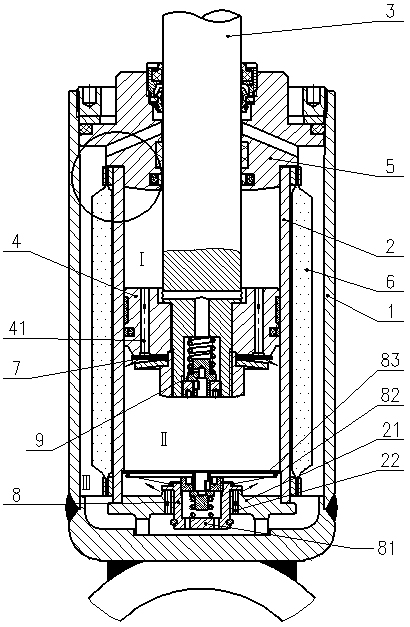
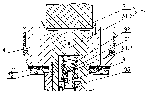
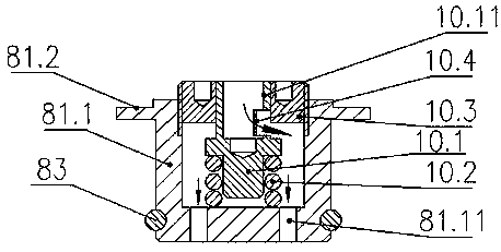
[0033] Combine below Figure 1 to Figure 4 Embodiments of the present invention are described in detail.

[0034] The hydraulic shock absorber includes an oil storage cylinder 1, a pressure cylinder 2 arranged in the oil storage cylinder 1, a piston rod 3 extending into the pressure cylinder 2 at one end, a piston 4 located in the pressure cylinder 2 and connected to the piston rod 3, The guide seat 5, which seals with the top of the oil storage cylinder 1 and guides and supports the movement of the piston rod 3, extends into the pressure cylinder 2 and abuts against the top surface of the pressure cylinder 2. The piston 4 divides the pressure cylinder 2 into two parts. The piston upper chamber I above the piston 4 and the piston lower chamber II below the piston 4 form an oil storage chamber III between the storage cylinder oil 1 and the pressure cylinder 2. The oil storage chamber III has a sealed air bag 6, and the piston The rod 3 is equipped with a stretch throttle elast...


PUM


Abstract

An oil damper comprises an oil storage cylinder, a pressure cylinder, a piston rod, a piston and a guide seat. The pressure cylinder is divided into a piston upper cavity and a piston lower cavity through the piston. An oil storage cavity is formed between the oil storage cylinder and the pressure cylinder. An inflation bag is arranged in the oil storage cavity, and a stretching throttling elasticvalve bank communicating with the oil storage cavity and the piston lower cavity when the piston rod stretches out is mounted at the bottom of the pressure cylinder. A compression damping adjusting elastic valve bank communicating with the piston lower cavity and the piston upper cavity when the piston rod is pressed in is mounted at the inner end of the piston rod. A compression unloading adjusting elastic valve bank communicating with the piston lower cavity and the oil storage cavity when the piston rod is pressed in is mounted at the bottom of the pressure cylinder. The rigidity of the compression damping adjusting elastic valve bank is smaller than that of the compression unloading adjusting elastic valve bank. According to the oil damper, different damping adjusting needs can be provided, and the oil damper is effective, reliable and stable in performance. The invention further provides a design method of the oil damper.

Description

technical field [0001] The invention relates to an oil pressure shock absorber and a design method thereof, belonging to the technical field of oil pressure shock absorbers. Background technique [0002] As a class A component of rolling stock and EMUs, the importance of hydraulic shock absorbers is increasingly recognized by the vast number of rolling stock scientific and technological workers. Whether it can normally exert its damping effect is directly related to the safety and comfort of rolling stock . When the hydraulic shock absorber is working, the piston reciprocates in the inner cylinder, forcing the hydraulic oil to flow through the damping hole to generate damping force. At the same time, the hydraulic shock absorber converts the mechanical energy in the system into the heat energy of the hydraulic oil and dissipates it to the air. In order to attenuate the vibration of the rolling stock. The valve system structure is the core component of the hydraulic shock a...

Claims


Application Information

Patent Timeline
Patent Type & Authority Applications(China)
IPC IPC(8): F16F9/19F16F9/32F16F9/34F16F9/36F16F9/44
CPCF16F9/19F16F9/3207F16F9/3405F16F9/369F16F9/44
Inventor 王三槐戴谋军吴忠发
Owner 株洲联诚集团减振器有限责任公司
Why Eureka
Try Eureka