Sound source positioning method adopting fisheye lens, and equipment for method

A fisheye lens and sound source positioning technology, which is applied in positioning, direction finders using ultrasonic/sonic/infrasonic waves, microphones, etc., can solve the problems of not being able to cover large angles and narrow shooting ranges, and reduce costs and increase popularity sex, reducing the number of effects

Active Publication Date: 2019-11-12
上海声茵科技有限公司
View PDF6 Cites 4 Cited by
  • Summary
  • Abstract
  • Description
  • Claims
  • Application Information

AI Technical Summary

Problems solved by technology

[0002]At present, the traditional acoustic camera uses binaural microphones for positioning, and uses the beamforming method to locate the sound source, which has certain limitations. At the extreme position of the array, such as at the far right or left end of the array or even the top and bottom, and the sound source beyond this range will produce ghost images (that is, the position of the real sound source is completely inconsistent with the position of the sound source obtained by taking pictures) , therefore, the current traditional acoustic camera has the defect that the shooting range is narrow and it cannot cover large angles

Method used


Image

  • Sound source positioning method adopting fisheye lens, and equipment for method
  • Sound source positioning method adopting fisheye lens, and equipment for method
  • Sound source positioning method adopting fisheye lens, and equipment for method

Examples


Embodiment 1

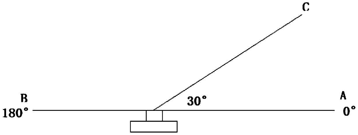
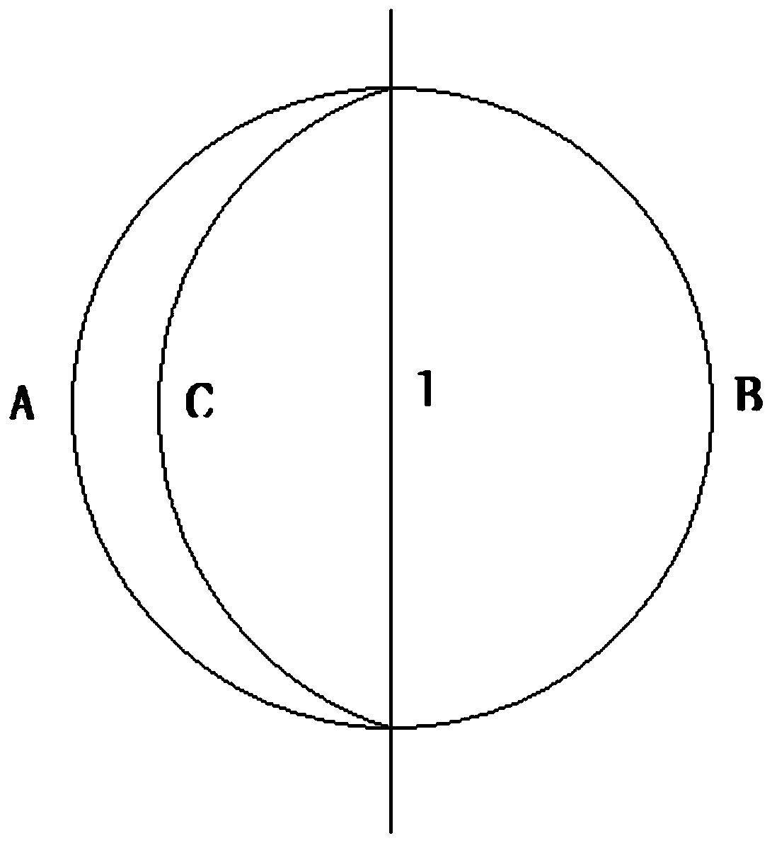
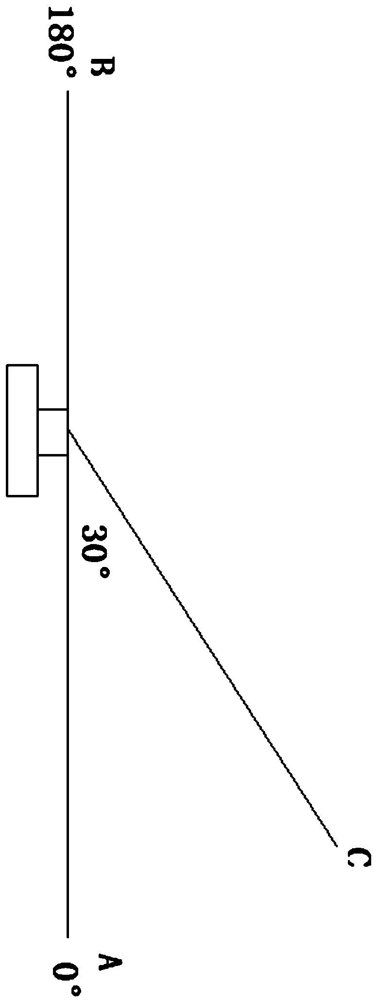
[0035] This embodiment first provides a database scanning method, which is more suitable for arrays with a large number of microphones, including spherical arrays. The main idea is to calculate in advance the distance difference between all relevant spatial positions and each pair of microphones in the array and establish a database. , if the database is scanned and the distance difference of several sound sources is found to be consistent with the value in the database, the current incident angle can be determined. Moreover, since the method adopted in this embodiment is to locate by calculating the incident direction of the sound wave, a fisheye lens is used in this way. The advantage of the fisheye lens is that it can be positioned 180 degrees up, down, left, and right. And when it is determined that the sound source distance difference between the sound source and the two microphones is a certain value, then all possible positions of the sound source are on a straight line,...

Embodiment 2

[0042] This embodiment provides another implementation of the technical solution, which is a direct calculation method, which does not need to set up a database and calibrate related data in advance, and is very economical to use on a small number of microphones. When the number of microphones is only a few When there are three (at least three), a single sound source can be localized by this method.

[0043] In this embodiment, the step a refers to obtaining the incident straight line or incident angle of the sound wave. Specifically, at least three microphones are set, and any two microphones form a pair of microphone groups, and any two pairs of microphone groups contain two microphones that are not completely the same, and the sound source distance difference between at least two pairs of microphone groups is calculated , and obtain the sound wave incidence surface of the sound wave relative to the microphone group through the sound source distance difference of any pair of...

Embodiment 3

[0049] This embodiment is an improvement based on Embodiment 2, so most of the content is the same as Embodiment 2, the only difference is that this embodiment is provided with at least four microphones, through at least four microphones, at least two incident sound waves can be obtained Straight line, the closest point or intersection point of any two incident straight lines of sound waves is the position of the sound source, from which the distance from the sound source to the fisheye camera can be obtained. Through the example of Embodiment 2, the position of the sound source in the imaging picture of the fisheye camera can be obtained, that is, a point in the imaging picture, and since a point in the imaging picture essentially represents a line in a three-dimensional space, therefore, Through the method of this embodiment, at least four microphones are set, and the distance between the sound source and the fisheye camera can be obtained while the position of the sound sour...


PUM


Abstract

The invention relates to the technical field of sound source positioning, in particular to a sound source positioning method adopting a fisheye lens, and equipment for the method. According to the method, by combining with the fisheye lens, a sound source is positioned through an incident straight line or an incident angle of a sound wave. The advantages of the sound source positioning method adopting the fisheye lens, and the equipment for the method include but not limited to the advantages that in general, the specific coordinates of the sound source are calculated without a formula by angle positioning instead of position positioning through the characteristics of the fisheye lens, so that an acoustic camera can realize wide-range and large-angle sound source positioning; and the number of microphones can be reduced through an algorithm, so that the acoustic camera is miniaturized, the cost can be greatly reduced, and the popularity of the acoustic camera is greatly improved.

Description

technical field [0001] The invention relates to the technical field of sound source localization, in particular to a sound source localization method and equipment using a fisheye lens. Background technique [0002] At present, the traditional acoustic camera uses binaural microphones for positioning, using the beamforming method to locate the position of the sound source, which has certain limitations. At the extreme position of the microphone array, such as at the far right or left end of the array Even the top and bottom, and sound sources beyond this range will produce ghost images (that is, the position of the real sound source is completely inconsistent with the position of the sound source obtained by taking pictures), so the current traditional acoustic camera has a narrow shooting range and cannot cover High angle flaws. Contents of the invention [0003] The purpose of the present invention is to solve the deficiencies of the prior art, and provide a sound sourc...

Claims


Application Information

Patent Timeline
IPC IPC(8): G01S5/24
CPCG01S5/24H04R1/406H04R3/005H04R1/342H04R2201/401H04R2430/21G01S3/802H04N23/635H04N23/698
Inventor 陈利君
Owner 上海声茵科技有限公司
Why Eureka
Try Eureka