


Quick Research
Generate reliable direction feasibility study reports for your R&D in just a few steps.

Technical Q&A
Discover and master advanced knowledge NOW. Basics, ideas, possibilities, all at once.

Find Solutions
As an expert in R&D theories, this can generate solutions to your technical problems instantly.

Evaluate Feasibility
Analyze your overall solution with one click, know your potential R&D risks in advance.

Monitor Landscape
Get weekly tech updates, stay abreast of the latest tech innovations and key insights.
Screen laminating method and display screen
A display and screen technology, applied in the field of display, can solve the problems of weak viscosity of liquid optical glue, difficult to fix stress display module, poor display, etc., to improve display effect, save process time, and avoid inconvenient operation. Effect
- Summary
- Abstract
- Description
- Claims
- Application Information
AI Technical Summary
Problems solved by technology
Method used
Image


Examples
Embodiment 1
[0044] figure 1 It is a flow chart of the screen pasting method provided by the embodiment of the present invention, figure 2 It is a schematic diagram of the front structure of the display screen provided by the embodiment of the present invention, image 3 It is a schematic diagram of the side view structure of the display screen during the screen bonding process provided by the embodiment of the present invention, Figure 4 For a schematic diagram of the side view structure of the display screen in another process of screen bonding provided by the embodiment of the present invention, refer to Figure 1-Figure 4 As shown, the embodiment of the present invention provides a method for bonding screens.
[0045] The screen bonding method provided by the embodiment of the present invention includes the following steps:
[0046] S101 , coating liquid optical glue on the cover glass 100 .
[0047] The cover glass 100 is used to form a display screen together with the display m...
Embodiment 2
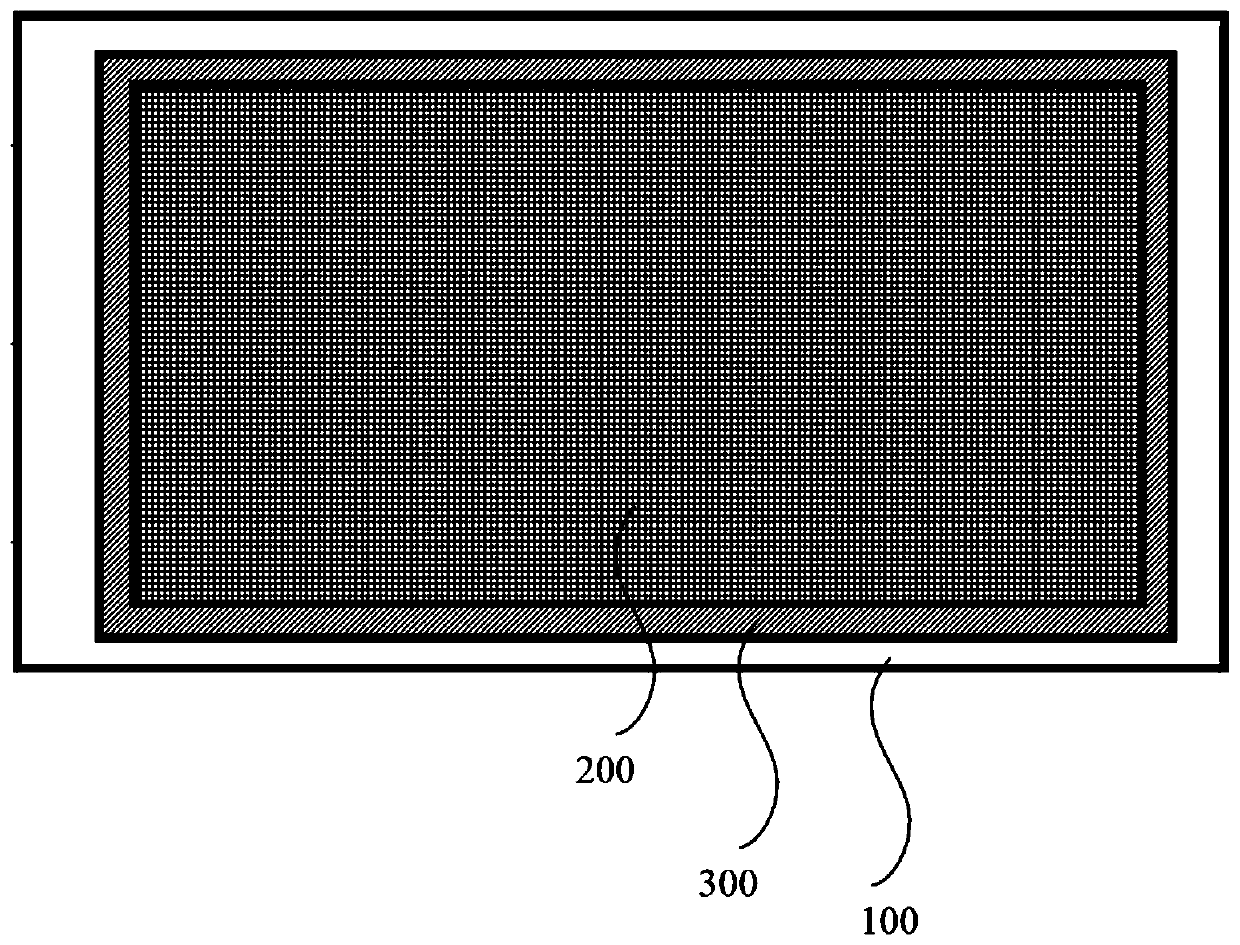
[0084] refer to figure 2 and Figure 4 As shown, the embodiment of the present invention provides a display screen, which is manufactured based on the screen bonding method described in the above embodiment, including: cover glass 100 and display module 400, cover glass 100 and display module 400 are connected through the optical adhesive layer 200 and the structural edge sealing adhesive 300 , and the structural edge sealing adhesive 300 is located at the periphery of the optical adhesive layer 200 .
[0085] Specifically, the cover glass 100 is used together with the display module 400 to form a display screen, wherein the cover glass 100 may be a capacitive screen cover of a touch module, and at this time, the display screen has a touch function.
[0086] In order to solve the problems such as whitening of the display screen, poor contrast and clarity caused by the air gap between the cover glass 100 and the display module 400, in this embodiment, an optical glue with a r...
PUM
 Abstract
Description
Claims
Application Information
 - R&D Engineer
- R&D Manager
- IP Professional
- Industry Leading Data Capabilities
- Powerful AI technology
- Patent DNA Extraction
Browse by: Latest US Patents, China's latest patents, Technical Efficacy Thesaurus, Application Domain, Technology Topic, Popular Technical Reports.
© 2024 PatSnap. All rights reserved.Legal|Privacy policy|Modern Slavery Act Transparency Statement|Sitemap|About US| Contact US: help@patsnap.com