
Optimal state trajectory control method for LLC converter adapting to rapid load mutation

An optimal state and trajectory control technology, which is applied in the direction of control/regulation system, output power conversion device, DC power input conversion to DC power output, etc.

Active Publication Date: 2019-11-12
NANJING UNIV OF AERONAUTICS & ASTRONAUTICS +1
View PDF5 Cites 4 Cited by
  • Summary
  • Abstract
  • Description
  • Claims
  • Application Information

AI Technical Summary

Problems solved by technology

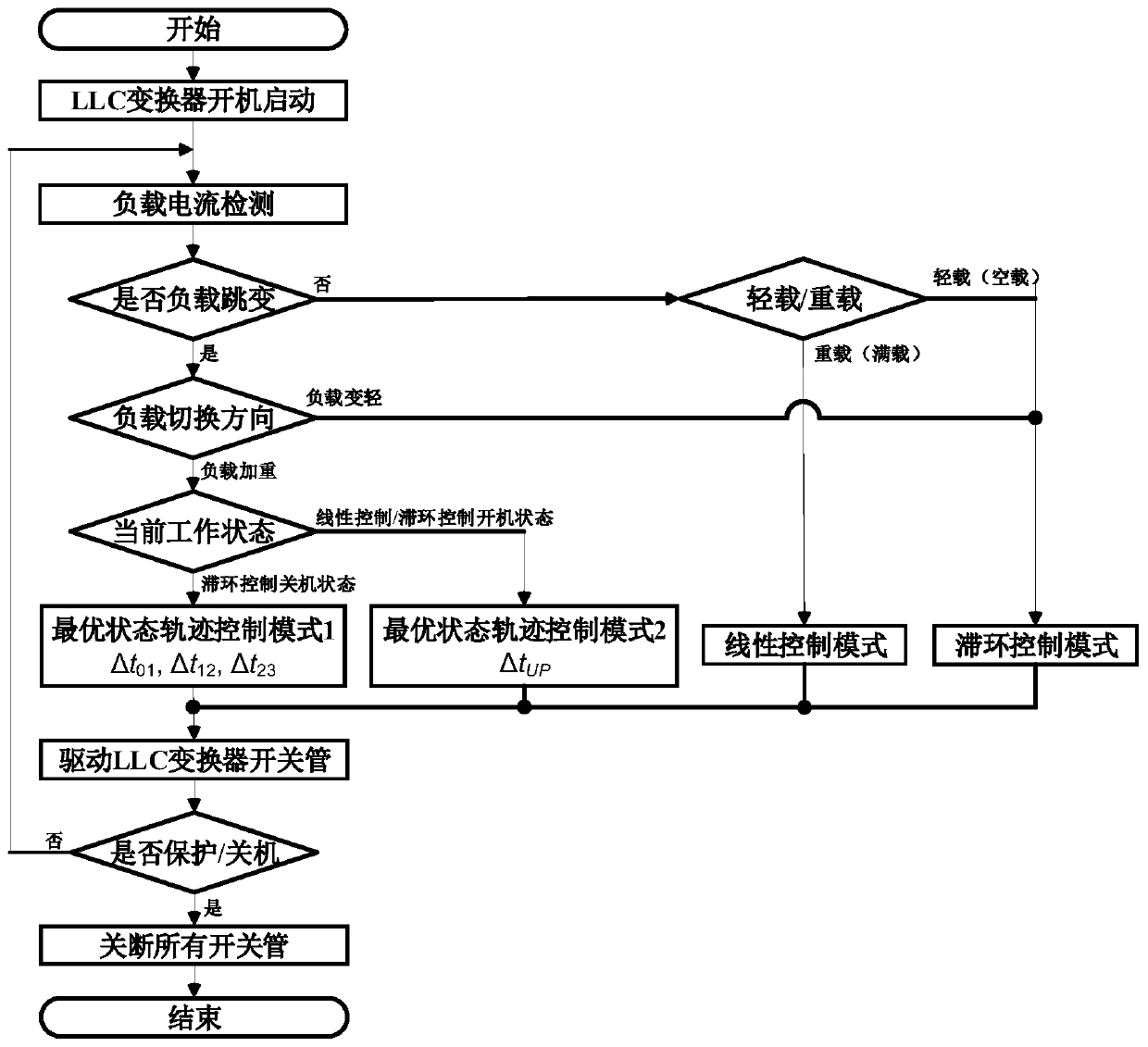
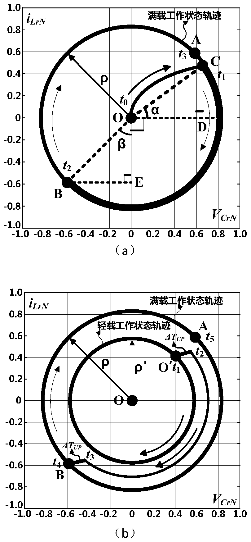
[0004] Aiming at the defects and deficiencies of the existing LLC resonant converter control method, which have poor load transient response and cannot meet the working requirements of pulse-type loads, the present invention provides an optimal state trajectory control method for LLC converters that adapts to rapid load mutations. Identify changes in the load state of the LLC resonant converter, and use optimal state trajectory control to quickly adjust the state variables of the LLC resonant converter to the target operating point, solving the problem of smoothing the LLC resonant converter from completely no-load (or very light load) to full load. Switching problem, fast dynamic response speed under load transient conditions, realizes stable and reliable operation of LLC resonant converter under pulse load conditions

Method used


Image

  • Optimal state trajectory control method for LLC converter adapting to rapid load mutation
  • Optimal state trajectory control method for LLC converter adapting to rapid load mutation
  • Optimal state trajectory control method for LLC converter adapting to rapid load mutation

Examples


Embodiment 1

[0093] Embodiment 1: Pulse-type load LLC resonant converter based on optimal state trajectory control of the present invention:

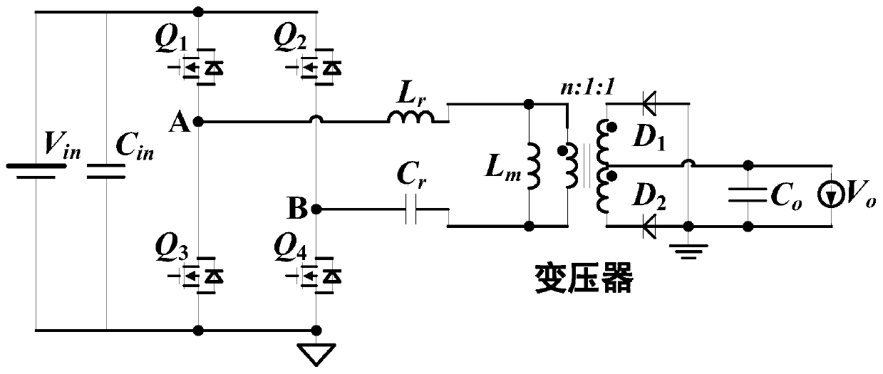
[0094] figure 1 Shown is the full-bridge LLC resonant converter as the controlled object, including the first switching tube Q 1 , the second switching tube Q 2 , the third switching tube Q 3 , the fourth switching tube Q 4 , Resonant inductance L r , Resonant capacitance C r , Transformer excitation inductance L m , a transformer with a turn ratio of n:1:1, the first diode D1, the second diode D2, and the input capacitor C in , output capacitance C o , input voltage V in and the output voltage V o , the first switching tube Q 1 and the third switching tube Q 3 The first bridge arm is formed in series, and the second switching tube Q 2 with the fourth switch Q 4 connected in series to form the second bridge arm, where the switching tube Q 1 -Q 4 Both are MOS tubes; resonant inductance L r , Resonant capacitance C r And a transformer...

Embodiment 2

[0101] Embodiment 2: Dynamic load matrix transformer LLC resonant converter based on optimal state trajectory control of the present invention:

[0102] Based on the circuit in Embodiment 1, this example provides an LLC resonant converter with a matrix transformer, such as Figure 9 shown. Compared with Embodiment 1, this embodiment mainly changes the transformer. The transformer is composed of a matrix transformer. The primary side windings of four separate transformers are connected in series to form the primary side of the matrix transformer. The secondary windings of the four transformers are respectively connected to form two rectifier diodes. The full-wave rectifier circuits are connected in parallel. Same as the first embodiment, the present embodiment enables the LLC resonant converter to have a good dynamic response to high di / dt transient loads such as pulse loads by using optimal state trajectory control, and can work stably under sudden load conditions. The desig...


PUM


Abstract

The invention discloses an optimal state trajectory control method for an LLC converter adapting to rapid load mutation. In the method, the state variable of the converter is rapidly adjusted to a target working point by using optimal state trajectory control through recognizing the change of the load state of the LLC resonant converter. The method is rapid in dynamic response speed under the condition that the load current is changed rapidly, and the LLC resonant converter can work stably and reliably under the condition of rapid load mutation such as the pulse type load.

Description

technical field [0001] The invention belongs to the technical field of power electronic converters, and relates to an optimal state trajectory control method of an LLC converter adapting to rapid load mutations. Background technique [0002] The development of modern radar technology requires more and more diversification and specialization of power supply. The working characteristics of radar determine that the load characteristic of its DC power supply is a pulse load, which is the worst dynamic load. By increasing the DC bus voltage (1kV), a smaller current can be achieved under the same power level, thus improving the power transmission and distribution efficiency of the power supply system. Therefore, on radar platforms such as ships, the high-voltage DC bus and the corresponding high-voltage, high-power-density DC-DC converters are an inevitable trend of development. [0003] The LLC resonant converter topology is currently the most commonly used high-voltage input, l...

Claims


Application Information

Patent Timeline
Patent Type & Authority Applications(China)
IPC IPC(8): H02M3/335
CPCH02M3/33507H02M3/33569H02M1/0012Y02B70/10
Inventor 张之梁姚恺奇唐家承徐志巍朱文铭任小永陈乾宏
Owner NANJING UNIV OF AERONAUTICS & ASTRONAUTICS
Learn More