
Cleaning system of prefabricated part annular production line

A technology of cleaning system and prefabricated components, applied in the field of cleaning system, can solve the problems of incomplete precipitation of concrete, low efficiency, sanitary and dirty production line, etc., and achieve the effect of optimizing the overall cleaning process, reducing occupation and waste, and improving the cleaning process

Pending Publication Date: 2019-11-15
CHANGSHA BROAD HOMES IND FUYANG CO LTD
View PDF1 Cites 1 Cited by
  • Summary
  • Abstract
  • Description
  • Claims
  • Application Information

AI Technical Summary

Problems solved by technology

[0004] 1) There are few cleaning links in the entire production cycle, which will easily cause the concrete to solidify and agglomerate in the feeding trolley and hopper, resulting in inconvenience for subsequent transportation, reduced efficiency, and increased difficulty in thorough cleaning;
[0005] 2) There is no sewage sedimentation tank in the mixing station area, the discharge port of the mixing station cannot be cleaned regularly, and the cleaning sewage of the hopper and the concrete feeding trolley cannot be collected, deposited and reused;
[0006] 3) Due to the single cleaning site, the hopper cleaning link affects the production efficiency of the production line and disrupts the production rhythm;
[0007] 4) The sedimentation structure of the cleaning tank in the existing material distribution area is single, the height of the bottom of the cleaning tank is consistent, and the design is too simple, which easily leads to incomplete precipitation of concrete and low recycling rate of sewage;
[0008] 5) Due to the small sedimentation area of ​​the cleaning tank in the fabric distribution area, the sedimentation takes a long time, which affects the production rhythm and progress of the production line, resulting in low production efficiency;
[0009] 6) Due to the short length of the distribution frame, the distribution hopper cannot be completely located directly above the cleaning pool in the distribution area even after the distribution hopper is moved to the end of the distribution machine near the cleaning pool in the distribution area. As a result, all the cleaning sewage cannot fall into the cleaning pool in the distribution area. Easy to cause hygienic and dirty problems in the production line

Method used


Image

  • Cleaning system of prefabricated part annular production line
  • Cleaning system of prefabricated part annular production line
  • Cleaning system of prefabricated part annular production line

Examples


Embodiment 1

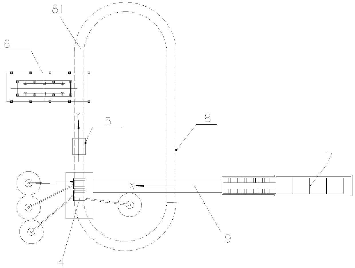
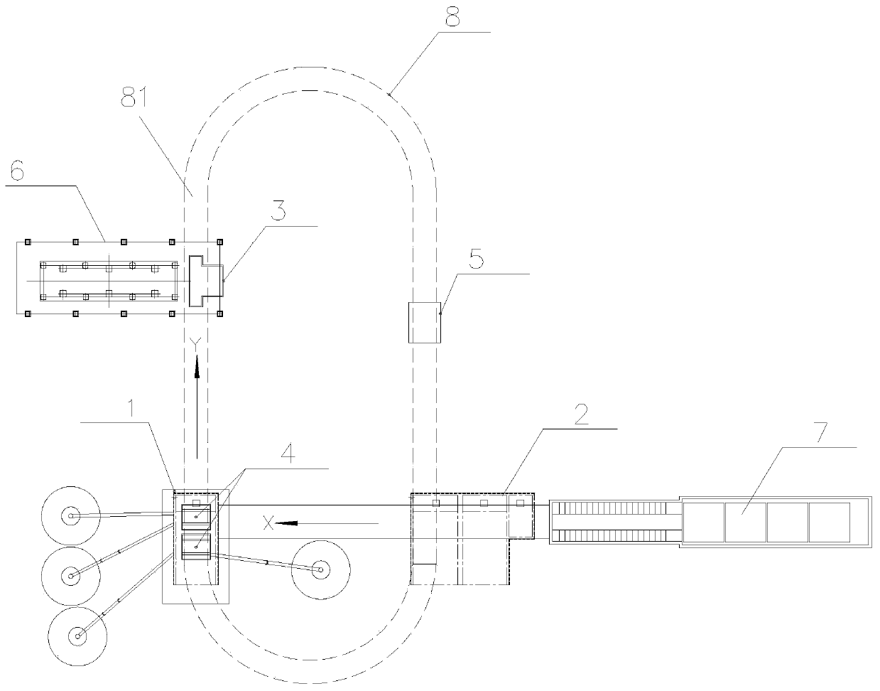
[0044] Such as figure 2As shown, the cleaning system of the circular production line of prefabricated components in this embodiment includes a first settling tank 1 for cleaning the hopper of the mixing station host 4, a first settling tank group 2 for cleaning the feeding car 5, And the second settling tank group 3 for cleaning the hopper on the cloth frame 6.

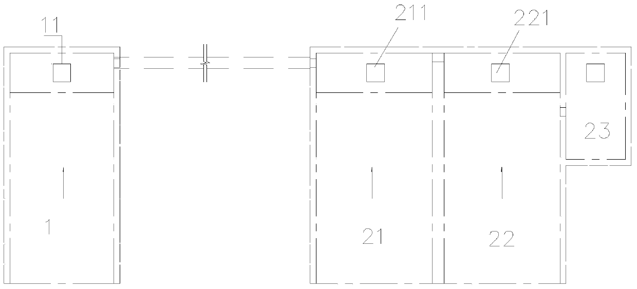
[0045] The first settling tank 1 is located below the main machine 4 of the mixing station, and the first settling tank group 2 is located between the main machine 4 of the mixing plant and the silo 7 of the mixing station and is positioned under the annular feeding rack 8; the first settling tank 1 and the first settling tank The pool groups 2 are communicated with each other through drains 9 .

[0046] Such as image 3 As shown, the first settling tank group 2 includes the second settling tank 21, the third settling tank 22 and the fourth settling tank 23 connected in sequence, the first settling tank 1, the seco...


PUM


Abstract

The invention discloses a cleaning system of a prefabricated part annular production line. The system comprises a first settling pond for cleaning a hopper of a stirring station main engine, a first settling pond set for cleaning a feeding car, and a second setting pond set for cleaning a hopper on a cloth rack. Accordingly, cleaning links are set at three different joints in the concrete transporting process, the production line cleaning pressure is relieved, occupation and waste of the production time is lowered, meanwhile, the settling area is enlarged, concrete sewage is promoted to be settled completely, clean sewage can be recycled, the production takt is not affected, the production links are more efficient and centralized.

Description

technical field [0001] The invention belongs to the technical field of prefabricated component production equipment, and in particular relates to a cleaning system for a circular production line of prefabricated components. Background technique [0002] CN201821667931.7 discloses a feeding system for a concrete placing machine, which includes an annular feeding frame 8 with an annular track, a feeding cart 5 located on the annular track, and a plurality of distribution racks 6 arranged at intervals under the annular track of the feeding frame. The feeding frame 6 is located at the end of the circular track and is provided with a mixing station docking position for docking with the mixing station main engine 4. The lower hopper of the mixing main engine of the mixing station is located directly above the docking position, and the feeding port of the feeding car 5 is located at the The docking position of the mixing station can be docked with the discharge port of the mixing s...

Claims


Application Information

Patent Timeline
Patent Type & Authority Applications(China)
IPC IPC(8): B01D21/02B28B17/00
CPCB01D21/02B28B17/00
Inventor 张剑陈韶临谢忠全屈璐
Owner CHANGSHA BROAD HOMES IND FUYANG CO LTD
Learn More