Sewage settling pond

A sedimentation tank and sewage technology, applied in the sedimentation tank and other directions, can solve the problems of slow sedimentation and long cleaning cycle of natural sedimentation, and achieve the effect of easy cleaning, simple and convenient operation and convenient maintenance.

Active Publication Date: 2019-11-15
中电建十四局城市建设投资有限公司
View PDF7 Cites 0 Cited by
  • Summary
  • Abstract
  • Description
  • Claims
  • Application Information

AI Technical Summary

Problems solved by technology

[0004] In the sedimentation tanks in the prior art, the particulate matter mainly depends on natural precipitation, and the sedimentation speed of natural sedimentation is relatively slow, and the particulate matter forms sludge after sedimentation. When the sludge is cleaned, a long cleaning period is required, and the sedimentation tank needs to be maintained during the period. shut down

Method used


Image

  • Sewage settling pond
  • Sewage settling pond
  • Sewage settling pond

Examples


Embodiment 1

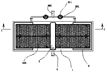
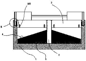
[0042] refer to Figure 1 to Figure 9 The shown sewage sedimentation tank includes a pool body 1 formed by pouring concrete, and a channel 2 is poured at the central position of the pool body 1, and the pool body 1 forms left and right sides under the separation of the channel 2. Two sedimentation chambers 3 that are not connected to each other are provided with overflow tanks 201 on the left and right sides of the channel 2. When the water level in the sedimentation tank 3 reaches the position of the overflow tank 201, it overflows into the channel 2. An outlet pipe 4 is embedded in the passage 2, and the outlet pipe 4 penetrates to the outside of the pool body 1. The height of the outlet pipe 4 is lower than the height of the overflow tank 201, and the overflow tank 201 V-shaped overflow outlets 211 are evenly distributed on the bottom of the tank, and more than one intercepting device 5 is arranged in each of the settling chambers 3;

[0043] Interception device 5 comprise...

Embodiment 2

[0046] refer to Figure 10~12 As shown, an L-shaped baffle plate 212 is welded at the inner left and right end faces of the passage 2, and the front and rear ends of the baffle plate 212 are welded with the inner front and rear end faces of the passage 2 to form a seal. A transition cavity 213 is formed on the inner side of the overflow tank 201, and the sewage entering from the overflow tank 201 flows into the interior of the channel 2 after passing through the transition cavity 213. A connection between the two channels is welded at the rear end of the channel 2. The U-shaped pipe 214 of the transition cavity 213, the U-shaped pipe 214 passes through the pool body 1, and the first connecting pipe 215 is welded on the outside of the U-shaped pipe 214, and the first connecting pipe 215 is installed with a second A ball valve 216, a cleaning pipe 217 is welded at the rear end of the channel 2, the cleaning pipe 217 extends to the outside of the pool body 1, and an end cap 218 i...

Embodiment 3

[0048] refer to Figure 13 As shown, slots 301 are provided at the front and rear inner walls of the precipitation chamber 3, the slots 301 extend downwards into the base 501, and a partition 302 is inserted in the slots 301, After the partition 302 is inserted, there is a gap of 5 cm to 20 cm between the bottom of the partition 302 and the upper surface of the interception plate 503, the lower end of the slot 301 is closed, and the upper end penetrates the pool upwards. Body 1, after the partition 302 is inserted, the height of the upper end surface of the partition 302 is higher than the height of the bottom of the overflow tank 201 .


PUM


Abstract

The invention discloses a sewage settling pond. The sewage settling pond comprises a pond body which is formed by pouring concrete, a channel is formed in the center of the pond body through pouring,the pond body is partitioned by the channel into a left settling chamber and a right settling chamber which are not communicated with each other, and overflow grooves are formed in the left and rightend faces of the channel; when the water level in the settling pond reaches the position of the overflow grooves, water overflows into the channel, and a water outlet pipe is embedded in and welded tothe channel, and penetrates to the outside of the pond body; the height of the water outlet pipe is lower than that of the overflow grooves, V-shaped overflow ports are uniformly distributed in the groove bottoms of the overflow grooves, and each settling chamber is internally provided with one or more interception devices. By means of the sewage settling pond, sludge can be quickly settled whilemachine halting can be omitted.

Description

technical field [0001] The invention relates to a sewage sedimentation tank. Background technique [0002] With the rapid development of society and economy, environmental pollution is becoming more and more serious, especially the urban environment is getting worse and worse, which has threatened people's production, life and human health. Therefore, people are increasingly aware of the importance of protecting the environment . Water is one of the most precious natural resources. Due to its limited nature, coupled with the rapid growth of population and the waste and pollution of water resources caused by industrial production, people's water consumption and water safety are seriously affected. Therefore, everyone should pay attention to the protection and rational use of water resources, and recycle and reuse water resources such as waste water and sewage in a scientific way. [0003] In the prior art, sedimentation tanks are usually used for primary filtration of sewag...

Claims


Application Information

Patent Timeline
Patent Type & Authority Applications(China)
IPC IPC(8): B01D21/02
CPCB01D21/02
Inventor 严幼仙马勇
Owner 中电建十四局城市建设投资有限公司
Why Eureka
Try Eureka