Supercharge Your Innovation With Domain-Expert AI Agents!

Shell cleaning control system for numerical control machine tool

A technology of CNC machine tools and control systems, which is applied in the direction of manufacturing tools, metal processing machinery parts, maintenance and safety accessories, etc., can solve problems such as unfavorable cleaning of CNC machine tools, time-consuming and laborious cleaning, troublesome cleaning of CNC machine tool shells, etc., to improve cleaning efficiency As well as the cleaning effect and the effect of reducing the difficulty of cleaning

Inactive Publication Date: 2019-11-15
湖北世纪天一机械有限公司
View PDF5 Cites 2 Cited by
  • Summary
  • Abstract
  • Description
  • Claims
  • Application Information

AI Technical Summary

Problems solved by technology

[0003] After the shell of the existing CNC machine tool is oily and dusty on the surface, it is often cleaned with a hand-held rag, which is time-consuming and laborious, and it is not easy to wipe at the higher position of the machine tool, which makes it more troublesome to clean the shell of the CNC machine tool. It is not conducive to the cleaning of the shell of the CNC machine tool, and there are certain deficiencies

Method used


Image

  • Shell cleaning control system for numerical control machine tool
  • Shell cleaning control system for numerical control machine tool
  • Shell cleaning control system for numerical control machine tool

Examples


Embodiment 1

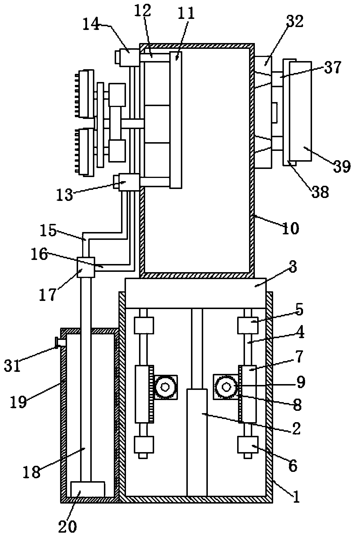
[0031] Embodiment one, such as Figure 1-2 As shown, a shell cleaning control system for a numerically controlled machine tool according to an embodiment of the present invention includes a cylinder-1, which is a cavity column, and a telescopic column is longitudinally arranged in the middle of the cylinder-1. 2. The top of the telescopic column 2 is provided with a push plate 3, and the push plate 3 is located at the opening position of the top of the column body 1, and both ends of the bottom of the push plate 3 are provided with support rods 4, so Both ends of the support rod 4 are provided with a limit sleeve 5 and a limit sleeve 6 respectively, wherein the limit sleeve 5 and the limit sleeve 6 are all fixed in the cylinder one 1 Both ends on both sides, both sides support bar 4 is provided with symmetrical half gear 7, and both sides half gear 7 corresponds to the side and is positioned at the middle part of both sides of described cylinder one 1 and is equipped with moto...

Embodiment 2

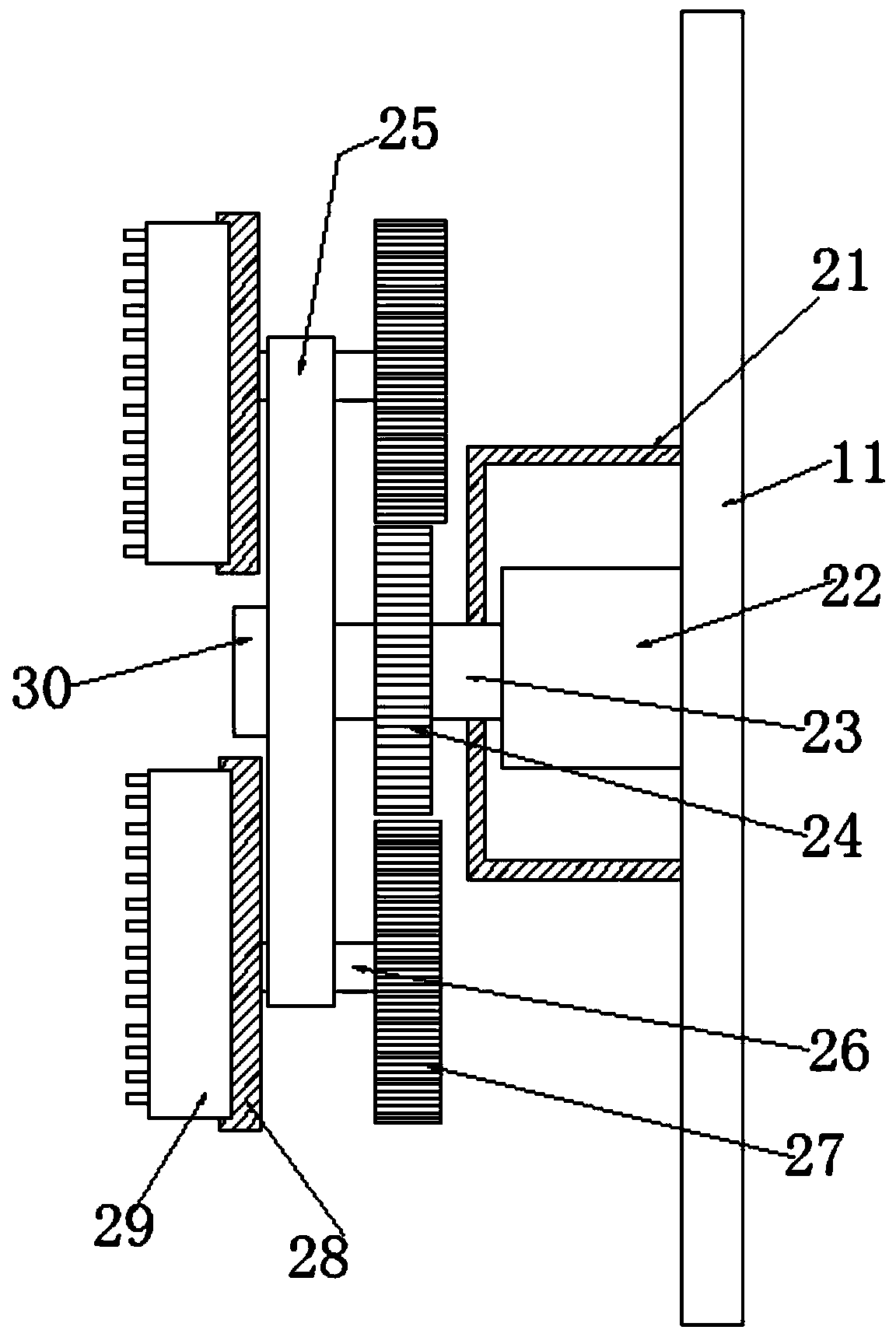
[0034] Embodiment two, such as figure 2As shown, the end of the rotating shaft 1 23 away from the motor 1 22 is sleeved with a limiting block 30 , and the sides of the limiting block 30 are fixed in the middle of the sides of the fixing plate 2 25 .

Embodiment 3

[0035] Embodiment three, such as figure 1 As shown, a water inlet 31 is provided on the top of the side of the water tank 19 away from the cylinder one 1, and a water inlet end cover is provided on the water inlet 31, wherein the diameter of the water inlet 31 is the same as that of the external inlet. The diameter of the water pipe is suitable.


PUM


Abstract

The invention discloses a shell cleaning control system for a numerical control machine tool. A first column is included and is a cavity column. A telescopic column is longitudinally arranged at the middle portion in the first column. A push plate is arranged on the top of the telescopic column and located at the top opening position of the first column. Supporting rods are arranged at the two ends of the bottom of the push plate. The two ends of each supporting rod are sleeved with a first limiting sleeve and a second limiting sleeve correspondingly, wherein the first limiting sleeve and thesecond limiting sleeve are fixed to the two ends of the two sides in the first column. The supporting rods on the two sides are provided with symmetric half gears, the corresponding side edges, located at the middle portions of the two sides in the first column, of the half gears on the two sides are provided with second motors, the output ends of the second motors are provided with complete gearsengaged with the half gears, and the top of the push plate is provided with a second column. The shell cleaning control system has the beneficial effects that the cleaning difficulty is lowered, effective cleaning is conveniently conducted on machine tool shells at different height positions, and time and labor are saved.

Description

technical field [0001] The invention relates to the technical field of shell cleaning application for numerical control machine tools, in particular to a shell cleaning control system for numerical control machine tools. Background technique [0002] Numerical control machine tool is the abbreviation of digital control machine tool, which is an automatic machine tool equipped with a program control system, which can logically process programs with control codes or other symbolic instructions, and decode them, using coded numbers It means that the numerical control device is input through the information carrier, and various control signals are sent by the numerical control device after calculation and processing to control the movement of the machine tool, and the parts are automatically processed according to the shape and size required by the drawing. When the numerical control machine tool is used, it is necessary to maintain the numerical control The cleanliness of the m...

Claims


Application Information

Patent Timeline
IPC IPC(8): B23Q11/00
CPCB23Q11/00
Inventor 沈祥斌
Owner 湖北世纪天一机械有限公司
Features
  • R&D
  • Intellectual Property
  • Life Sciences
  • Materials
  • Tech Scout
  • Unparalleled Data Quality
  • Higher Quality Content
  • 60% Fewer Hallucinations
Learn More