Eureka AIR delivers breakthrough ideas for toughest innovation challenges, trusted by R&D personnel around the world.

Automobile air conditioner compressor and tilting tray structure thereof

A technology for automotive air conditioners and compressors, which is applied in mechanical equipment, machines/engines, liquid variable capacity machines, etc. It can solve problems such as troublesome installation, and achieve the effects of convenient assembly, stable interference effect, and stable use

Inactive Publication Date: 2019-11-15
台州动林汽车空调压缩机有限公司
View PDF6 Cites 0 Cited by
  • Summary
  • Abstract
  • Description
  • Claims
  • Application Information

AI Technical Summary

Problems solved by technology

[0004] With the above-mentioned swash plate structure, when installing, first install the swash plate, return spring and rotating arm on the main shaft, and then pass the pin shaft through the pin sleeve and the waist hole, and fix the pin shaft so that The overall installation is troublesome and needs to be improved

Method used


Image

  • Automobile air conditioner compressor and tilting tray structure thereof
  • Automobile air conditioner compressor and tilting tray structure thereof
  • Automobile air conditioner compressor and tilting tray structure thereof

Examples


Embodiment

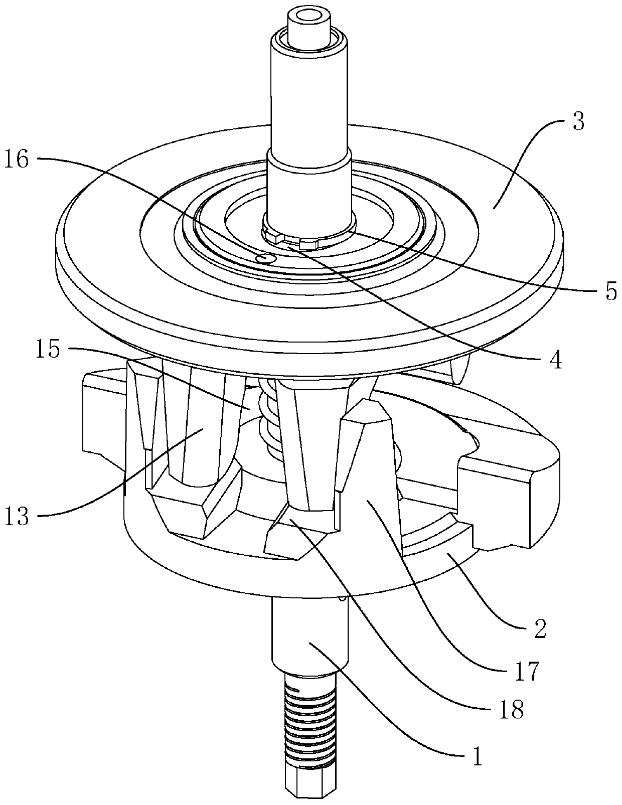
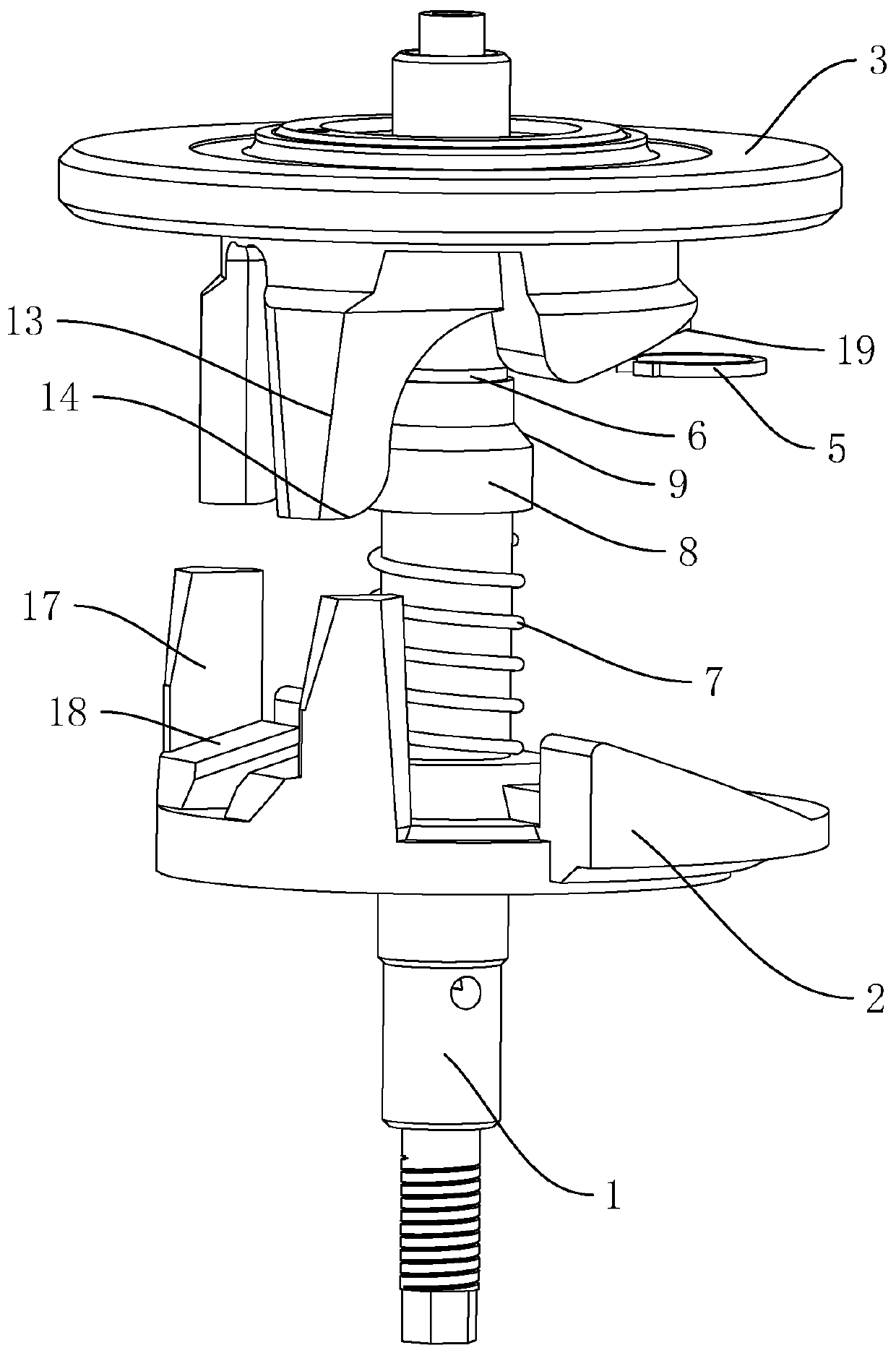
[0040] A swash plate structure of an automobile air-conditioning compressor, such as figure 1 As shown, it includes a main shaft 1 , a rotary arm 2 and a swash plate 3 arranged on the main shaft 1 . The pivoting arm 2 is coaxially fixed on the main shaft 1, and the center of the swash plate 3 is provided with an equi-cylindrical oblique hole 4 for the main shaft 1 to pass through.

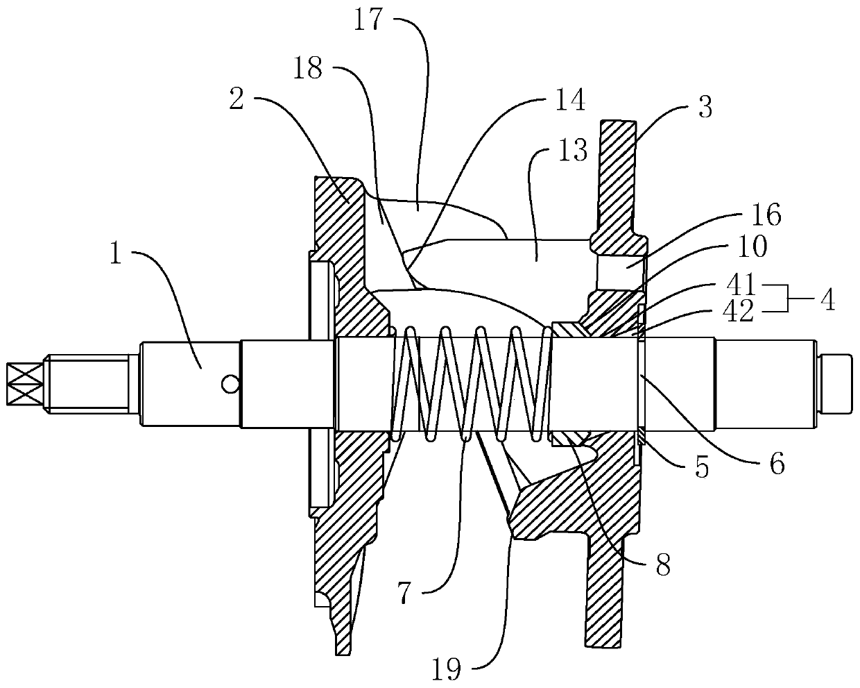
[0041] like figure 1 , image 3As shown, the equi-cylindrical oblique hole 4 includes a mounting hole 41 opened at the axial center of the swash plate 3 for the main shaft 1 to pass through, and two relief grooves 42 opened at both axial ends of the mounting hole 41 . The two relief grooves 42 are respectively located in the opposite direction of the inner wall of the installation hole 41, so that the two relief grooves 42 are respectively located on the radial sides of the main shaft 1. The space for the swash plate 3 to turn is provided by the relief grooves 42, so that the swash plate 3 The d...

Embodiment 2

[0049] A swash plate structure of an automobile air-conditioning compressor, which is different from Embodiment 1 in that the swash plate 3 is arranged in a split form. like Figure 5 As shown, the swash plate 3 includes a mounting seat 31 sheathed on the main shaft 1 and a disc body 32 fixed on the mounting seat 31 , the axis of the disc body 32 coincides with the axis of the main shaft 1 . The equi-cylindrical oblique holes 4 are arranged on the mounting seat 31, the mounting seat 31 includes a positioning convex ring 11, and the disk body 32 is correspondingly provided with a positioning groove 12 for the positioning convex ring 11 to be embedded, and the positioning convex ring 11 and the positioning groove The tight fit of 12 makes the disc body 32 and the mounting seat 31 fixedly connected together. The guide portion 13 , the limiting block 19 and the oil hole 16 are all located on the mounting seat 31 .

[0050] The split arrangement of the swash plate 3, because the ...

Embodiment 3

[0052] A car air-conditioning compressor, such as Image 6 As shown, including the body 20, the above-mentioned swash plate structure arranged in the body 20, the main shaft 1 is coaxially connected to the body 20, the body 20 is also provided with a piston 21 that cooperates with the swash plate 3, and the main shaft 1 passes through the body 20 One end of is connected with belt pulley 22. The pulley 22 is connected to the drive source to drive the main shaft 1 to rotate. When the main shaft 1 rotates, the swash plate 3 also rotates, and the edge of the swash plate 3 pushes the piston 21 to make axial reciprocating motions to realize compression, exhaust, expansion and suction. Work steps.


PUM


Abstract

The invention discloses a tilting tray structure of an automobile air conditioner compressor. According to the technical scheme, the tilting tray structure is characterized in that the tilting tray structure comprises a main shaft, a rotating arm arranged on the main shaft and a tilting tray; the rotating shaft is coaxially fixed to the main shaft, and an equal cylindrical oblique crossing hole isformed in the axis position of the tilting tray; a clamp ring is further connected to the main shaft in a clamped manner and is located on the side, away from the rotating arm, of the tilting tray, and a reset spring is further arranged between the tilting tray and the rotating arm; a guide portion is further arranged on the end face, close to the rotating arm, of the tilting tray, and the two side faces, parallel to the turnover direction of the tilting tray, of the guide portion are parallel to the turnover direction of the tilting tray; two locating portions are further arranged on the endface, close to the tilting tray, of the rotating arm and are arranged on the two outer sides of the guide portion correspondingly, and the opposite end faces of the two locating portions are parallel; and a limiting portion is further fixed to the rotating arm. Through cooperation and guide of the guide portion, the locating portions and the limiting portion, circumferential wear is reduced, limitation of a kidney-shaped hole to turnover is also avoided, the overall structure is simpler, and assembling is more convenient.

Description

technical field [0001] The invention relates to the field of automobile air-conditioning compressors, more specifically, it relates to an automobile air-conditioning compressor and its swash plate structure. Background technique [0002] Automobile air-conditioning compressor is the heart of automobile air-conditioning refrigeration system, which plays the role of compressing and transporting refrigerant. Among them, the swash plate type automobile air-conditioning compressor is a type widely used in automobile air-conditioning compressors. The swash plate is connected to the drive shaft at a certain angle, and the edge of the swash plate is fitted in the groove in the middle of the piston. When the drive shaft rotates, the swash plate also rotates, and the edge of the swash plate pushes the piston to reciprocate in the axial direction to realize the working steps of compression, exhaust, expansion and suction. Usually, when the compressor is at low speed or high load, the ...

Claims


Application Information

Patent Timeline
IPC IPC(8): F04B39/00F04B39/14F04B27/08
CPCF04B27/086F04B39/00F04B39/14
Inventor 游袁潘晓明潘国建
Owner 台州动林汽车空调压缩机有限公司
Why Eureka
Eureka Blog
Learn More