
Direct feed type wiredrawing speed reducer

A wire-drawing reducer, straight-forward technology, applied in the directions of transmission parts, belts/chains/gears, mechanical equipment, etc., can solve the problems that affect the quality of wire-drawing, cannot be closer to the wire-drawing parts, and affect the stability of wire-drawing work. The effect of improving rigidity, high transmission efficiency and improving stability

Pending Publication Date: 2019-11-15
ZHEJIANG TANHON DRIVING MACHINE
View PDF0 Cites 1 Cited by
  • Summary
  • Abstract
  • Description
  • Claims
  • Application Information

AI Technical Summary

Problems solved by technology

[0002] At present, the input and output of the reducer used in the straight wire drawing machine cannot bear large impact force. The upper shaft end of the output shaft is supported by the reducer box and cannot be closer to the drawing parts, which will affect the stability of the drawing work. In addition, the reducer does not have the speed measurement function, and the output speed of the reducer cannot be observed in real time, which affects the drawing quality

Method used


Image

  • Direct feed type wiredrawing speed reducer
  • Direct feed type wiredrawing speed reducer
  • Direct feed type wiredrawing speed reducer

Examples


Embodiment Construction

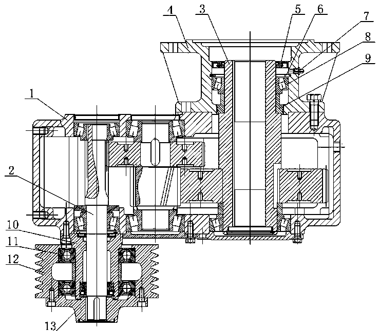
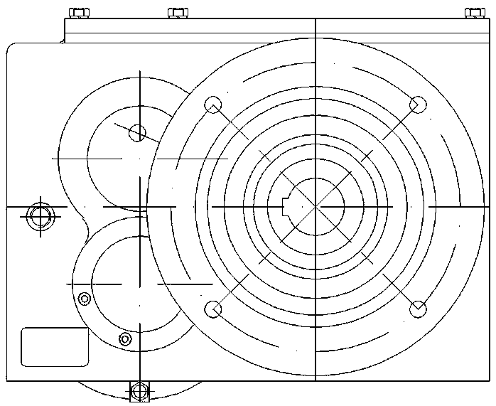
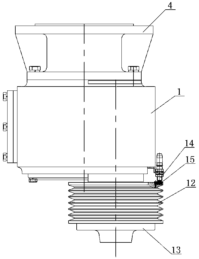
[0013] As shown in the figure, the linear drawing reducer of the present invention includes a box body 1 and an input shaft 2 and an output shaft 3 arranged vertically. The input shaft 2 transmits the output shaft 3 through gear reduction, and the upper shaft end of the output shaft 3 Rotation is supported by the tapered roller bearing 8 located in the inner hole of the connecting flange 4. The connecting flange 4 makes the upper shaft end of the output shaft 3 support higher than the top of the box body 1, and the connecting flange 4 is fixedly installed on the top of the box body 1. The upper end surface of the outer ring of the tapered rolling bearing 8 is axially limited by the retaining ring 6 for the hole, and the sealing ring 5 for sealing the shaft end of the output shaft 3 is arranged above the retaining ring 6 for the hole, and the sealing ring 5 and the tapered rolling bearing The inner hole wall of the connecting flange between 8 is provided with a grease injection ...


PUM


Abstract

The invention discloses a direct feed type wiredrawing speed reducer. The direct feed type wiredrawing speed reducer comprises a box body, a vertically-arranged input shaft and a vertically-arranged output shaft. The input shaft drives the output shaft through gear reduction. The direct feed type wiredrawing speed reducer is characterized in that the upper shaft end of the output shaft is rotationally supported by a rolling cone bearing arranged in an inner hole of a connecting flange, the upper shaft end of the output shaft is supported by the connecting flange to be higher than the top of the box body, the connecting flange is fixedly mounted on the top of the box body, the upper end face of the outer ring of the rolling cone bearing is axially limited through a retaining ring for a hole, a sealing ring for sealing the shaft end of the output shaft is arranged above the retaining ring for the hole, a grease injection opening is formed in the portion, between the sealing ring and therolling cone bearing, of the wall of the inner hole of the connecting flange, the inner hole of the connecting flange shrinks at the position of a lower port and is provided with an oil blocking ring,and the oil blocking ring is fixedly mounted on the outer circle of the output shaft. Both the input shaft and the output shaft can bear higher impact force, the upper shaft end of the output shaft is closer to a wiredrawing part, the stability of wiredrawing work is improved, and the direct feed type wiredrawing speed reducer has a speed measuring function.

Description

technical field [0001] The invention relates to a reducer specially used for a straight wire drawing machine. Background technique [0002] At present, the input and output of the reducer used in the straight wire drawing machine cannot bear large impact force. The upper shaft end of the output shaft is supported by the reducer box and cannot be closer to the drawing parts, which will affect the stability of the drawing work. In addition, the reducer does not have the speed measurement function, and the output speed of the reducer cannot be observed in real time, which affects the drawing quality. Contents of the invention [0003] In view of the deficiencies in the prior art, the purpose of the present invention is to provide a stronger impact force for both input and output, and the upper shaft end of the output shaft is also closer to the drawing part, which improves the stability of the drawing work and has its own speed measurement Functional in-line drawing reducer....

Claims


Application Information

Patent Timeline
Patent Type & Authority Applications(China)
IPC IPC(8): F16H57/021F16H57/04F16H37/02
CPCF16H57/021F16H57/0421F16H37/02
Inventor 龚学华郑招业唐小军缪茂浪柳圣杰
Owner ZHEJIANG TANHON DRIVING MACHINE
Learn More