Method for quantitative analysis of brightener in copper foil electrolyte

A quantitative analysis and brightener technology, which is applied in the direction of material analysis, material analysis, and material electrochemical variables through electromagnetic means, can solve problems such as unproposed solutions, and achieve the effect of simple operation

Active Publication Date: 2019-11-15
JIUJIANG TELFORD ELECTRONICS MATERIAL CO LTD
View PDF7 Cites 5 Cited by
  • Summary
  • Abstract
  • Description
  • Claims
  • Application Information

AI Technical Summary

Problems solved by technology

The premise of controlling additive consumption-compensation balance is to accurately track the concentration of additives in the electrolyte quantitatively, which is difficult to achieve with current general analysis methods
[0006] For the problems in related technologies, no effective solutions have been proposed yet

Method used


Image

  • Method for quantitative analysis of brightener in copper foil electrolyte
  • Method for quantitative analysis of brightener in copper foil electrolyte
  • Method for quantitative analysis of brightener in copper foil electrolyte

Examples


Embodiment 1

[0043] Take 50mL of the detection matrix solution to the reaction tank, connect the three-electrode system, and select the cyclic voltammetry to run the electrochemical workstation to obtain the initial voltammetry characteristic curve.

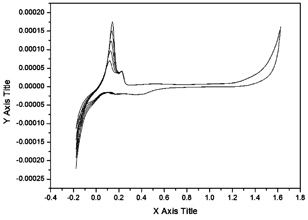
[0044] Add 1mL sample to the reaction tank, run the electrochemical workstation to obtain the volt-ampere characteristic curve after adding the sample, add 0.1mL brightener standard solution to the reaction tank three times, run the workstation respectively, and obtain a total of 5 volt-ampere characteristic curves as follows: figure 1 shown.

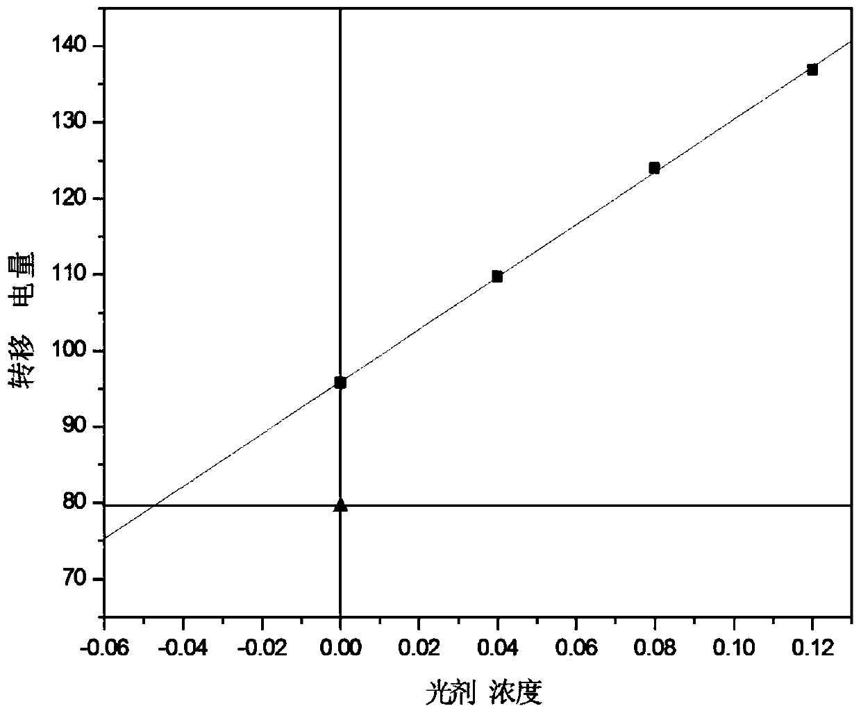
[0045] Process the volt-ampere characteristic curve, calculate the corresponding transfer electricity according to the integral area of ​​each curve, and obtain the brightener concentration-transfer electricity curve as figure 2 As shown, the correction determination coefficient R=0.99978≥0.999.

[0046] Calculate the concentration of brightener in the sample according to the intercept of the curve ...

Embodiment 2

[0048] Take 50mL of the detection matrix solution to the reaction tank, connect the three-electrode system, and select the cyclic voltammetry to run the electrochemical workstation to obtain the initial voltammetry characteristic curve.

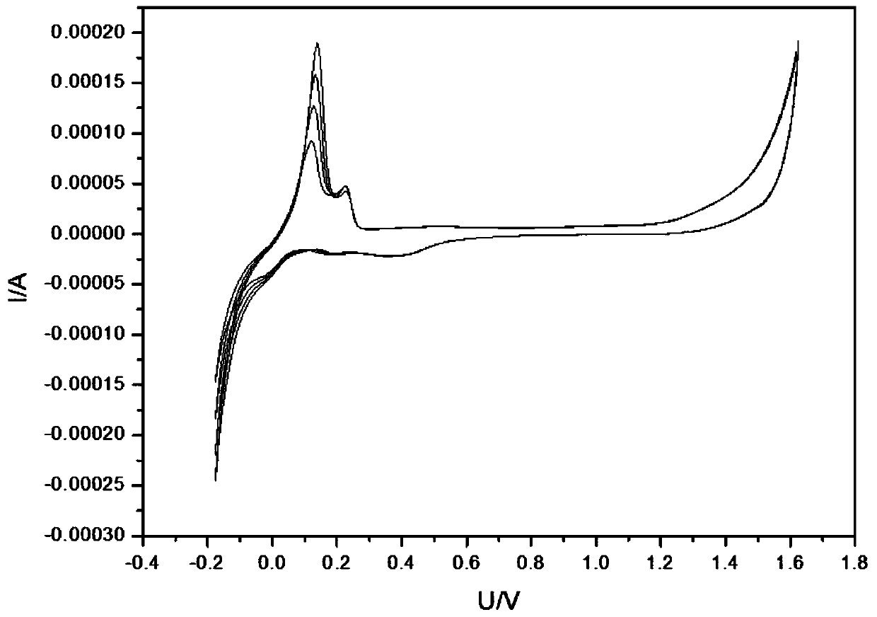
[0049]Add 1mL sample to the reaction tank, run the electrochemical workstation to obtain the volt-ampere characteristic curve after adding the sample, add 0.1mL brightener standard solution to the reaction tank twice, run the workstation respectively, and obtain a total of 4 volt-ampere characteristic curves as follows: image 3 shown.

[0050] Process the volt-ampere characteristic curve, calculate the corresponding transfer electricity according to the integral area of ​​each curve, and obtain the brightener concentration-transfer electricity curve as Figure 4 As shown, the correction determination coefficient R=0.99924≥0.999.

[0051] Calculate the concentration of brightener in the sample according to the intercept of the curve

[...


PUM


Abstract

The invention discloses a method for quantitative analysis of a brightener in a copper foil electrolyte. The method comprises the following steps: preparing an imitation electrolyte, preparating a detection matrix solution, and preparating a brightener standard solution; adding a detection sample into a reaction tank containing the detection matrix solution and analyzing and recording previous andlater changes of a voltammetric characteristic curve by using the cyclic voltammetry; adding the brightener standard solution into the reaction tank after detection sample adding intermittently and recording a cyclic voltammetry curve before and after adding of the brightener standard solution each time; and drawing a sample test curve map and calculating the brightener concentration in the sample. According to the method, with the electrochemical analysis, interferences of various additives are eliminated by adjusting the matrix solution components based on the addition method. The method issuitable for detection of different high tensile formulas with the same brighteners. The method is operated simply after formation; and an effective monitoring way is provided for the high-tensile copper foil formula additive process.

Description

technical field [0001] The invention relates to the technical field of electrolytic copper foil production, in particular to a quantitative analysis method for a brightener in a copper foil electrolyte. Background technique [0002] With the vigorous development of the new energy vehicle industry, the market demand for power batteries has been in a strong trend. As the negative electrode collector material of power batteries, the market demand for lithium battery copper foil has also been greatly driven. With the increasing production capacity of domestic lithium battery copper foil in recent years, the competition in the copper foil market has become increasingly fierce. However, high-end lithium battery copper foil products in the market have been in short supply, and are monopolized by a few overseas or overseas-backed companies such as Japan and Taiwan. The reason is that the overall domestic research and development level is low and innovation is not enough. Therefore...

Claims


Application Information

Patent Timeline
IPC IPC(8): G01N27/48G01N27/416
CPCG01N27/48G01N27/4166Y02E60/10
Inventor 范远朋黄雨晖
Owner JIUJIANG TELFORD ELECTRONICS MATERIAL CO LTD
Why Eureka
Try Eureka