Radar speed measurement equipment with debugging mechanism easy to assemble and disassemble

A radar speed measurement, easy loading and unloading technology, applied in measurement devices, radio wave measurement systems, radio wave reflection/re-radiation and other directions, can solve the problems of long construction period, high cost, single assembly method, etc., to achieve simple and convenient construction operation , Low cost and short construction period

Active Publication Date: 2019-11-15
安徽智立通科技股份有限公司
View PDF18 Cites 1 Cited by
  • Summary
  • Abstract
  • Description
  • Claims
  • Application Information

AI Technical Summary

Problems solved by technology

[0003] The technical problem to be solved by the present invention is: in order to solve the problems existing in the above-mentioned background technology, provide an improved radar speed measuring device with an easy-to-assemble and disassemble debugging mechanism, and solve the problem that most of the installation mechanisms of current radar speed measuring devices have simple and fixed structures and a single assembly method , and once the installation is completed, it cannot be adjusted at a low position, resulting in the problem that the early installation and later maintenance and replacement often require the auxiliary use of large-scale equipment, the construction period is long, and the cost is high

Method used


Image

  • Radar speed measurement equipment with debugging mechanism easy to assemble and disassemble
  • Radar speed measurement equipment with debugging mechanism easy to assemble and disassemble

Examples


Embodiment

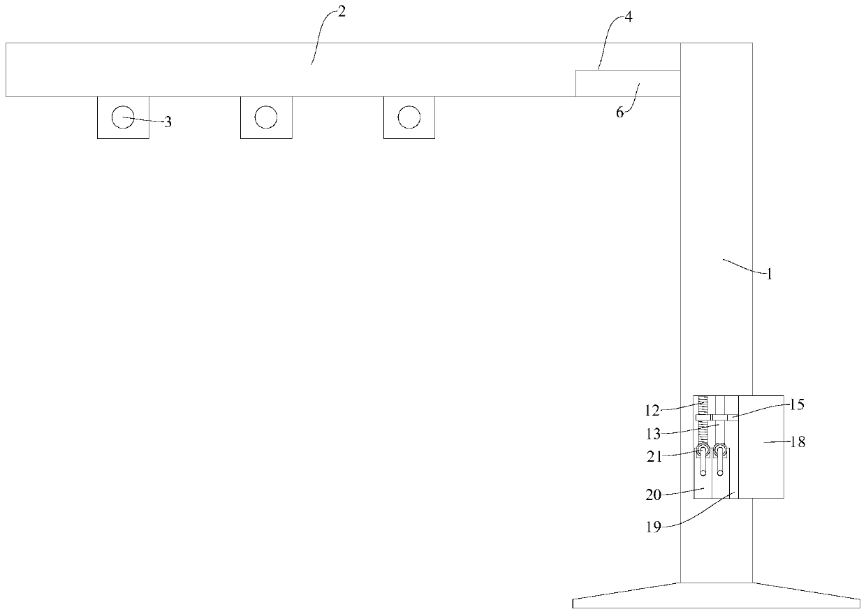
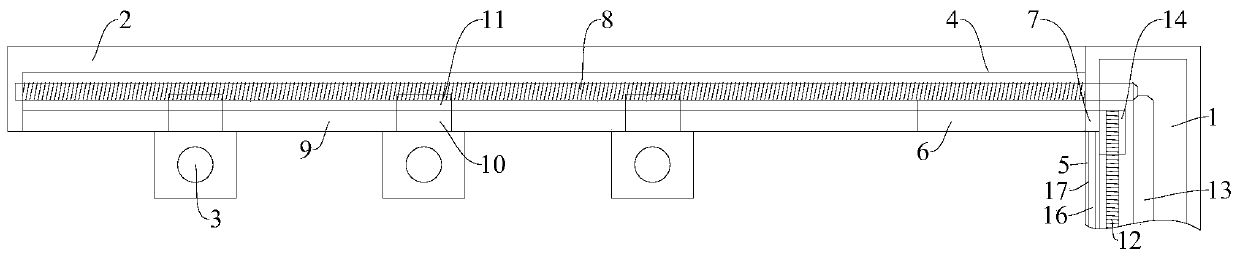
[0018] Embodiment: Turn the rotating shaft 21 upwards so that the bevel gear at the top of the rotating shaft 21 meshes with the bevel gears at the bottom end of the first vertical lifting screw 12 and the bottom end of the second longitudinal adjusting screw 13 at the corresponding positions, and then rotate To control the lifting and translation, the display controls the rotation of the second longitudinal adjustment screw rod 13, and then the second longitudinal adjustment screw rod 13 controls the rotation of the top external thread adjustment screw rod 8, and the top external thread adjustment screw rod 8 drives the radar speed measurement through rotation. The shooting device 3 moves from the lower end of the horizontal fixed rod 2 to the lower end of the bottom lifting seat 6, and then controls the rotation of the first vertical lifting screw rod 12, and the first vertical lifting screw rod 12 drives the bottom lifting seat 6 to lift, thereby driving the shooting equipmen...


PUM


Abstract

The invention relates to the technical field of radar speed measurement auxiliary installation, in particular to radar speed measurement equipment with a debugging mechanism easy to assemble and disassemble. The radar speed measurement equipment comprises a longitudinal fixed rod, a transverse fixed rod and shooting equipment for radar speed measurement, wherein the bottom of longitudinal fixed rod is fixedly arranged at one side of a road, the transverse fixed rod is welded and fixed onto a side surface of the top of the longitudinal fixed rod, and a bottom assembly groove is formed in a right side of a lower surface of the transverse fixed rod. In the radar speed measurement equipment with the debugging mechanism easy to assemble and disassemble, a bottom lifting seat is controlled to ascend and descend and a top external threaded adjustment lead screw is controlled to rotate respectively by a first longitudinal lifting lead screw and a second longitudinal lifting lead screw, so thatthe shooting equipment for radar speed measurement movably connected to a translation opening in the bottom of a lower end of the transverse fixed rod is controlled to translate, ascend and descend,the assembly, disassembly and adjustment of the shooting equipment for radar speed measurement does not dependent on large-size lifting equipment and can be completed only by a worker to operate at the bottom, the construction operation is simple and convenient, the construction period is short, and the cost is low.

Description

technical field [0001] The invention relates to the technical field of radar speed measurement auxiliary installation, in particular to a radar speed measurement device with an easy-to-assemble and disassemble debugging mechanism. Background technique [0002] Radar speed measurement mainly uses the principle of the Doppler effect: when the target approaches the radar antenna, the frequency of the reflected signal will be higher than the frequency of the transmitter; conversely, when the target moves away from the antenna, the frequency of the reflected signal will be lower than the frequency of the transmitted signal. machine frequency. In this way, the relative speed between the target and the radar can be calculated by changing the value of the frequency (the Doppler frequency is positive when the target is flying against the radar, and the Doppler frequency is negative when the target is flying away from the radar). It has been widely used in police speed testing and ot...

Claims


Application Information

Patent Timeline
Patent Type & Authority Applications(China)
IPC IPC(8): G01S13/58G01S7/02G01S13/86
CPCG01S13/58G01S7/02G01S13/867
Inventor 杨开敏
Owner 安徽智立通科技股份有限公司
Why Eureka
Try Eureka